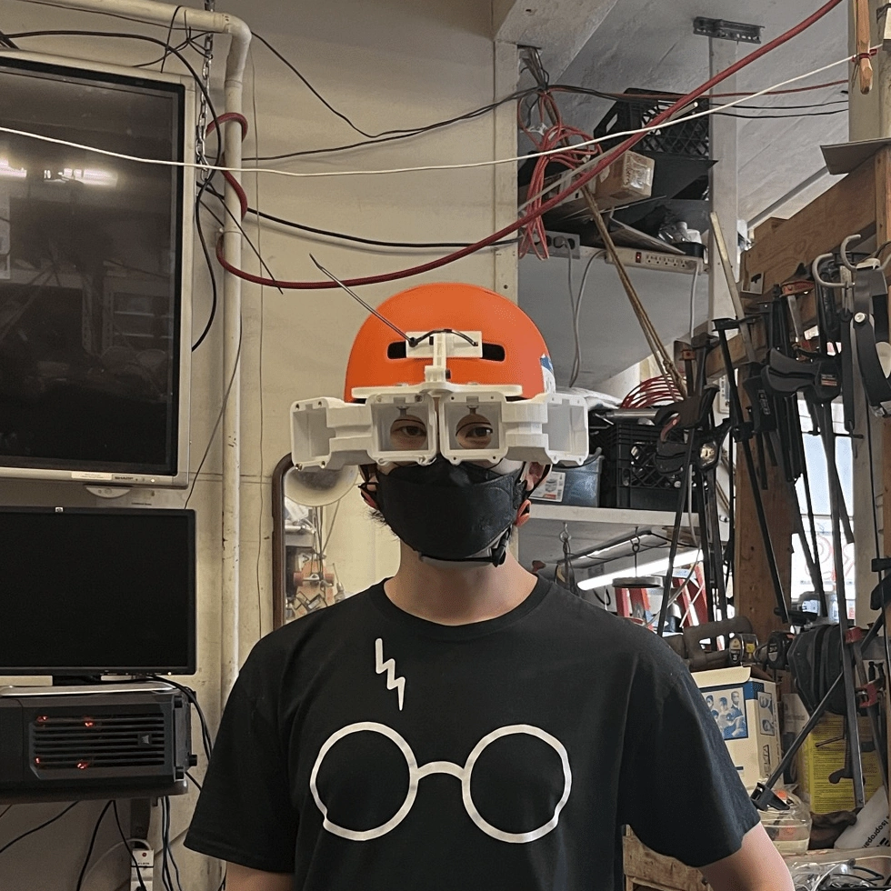
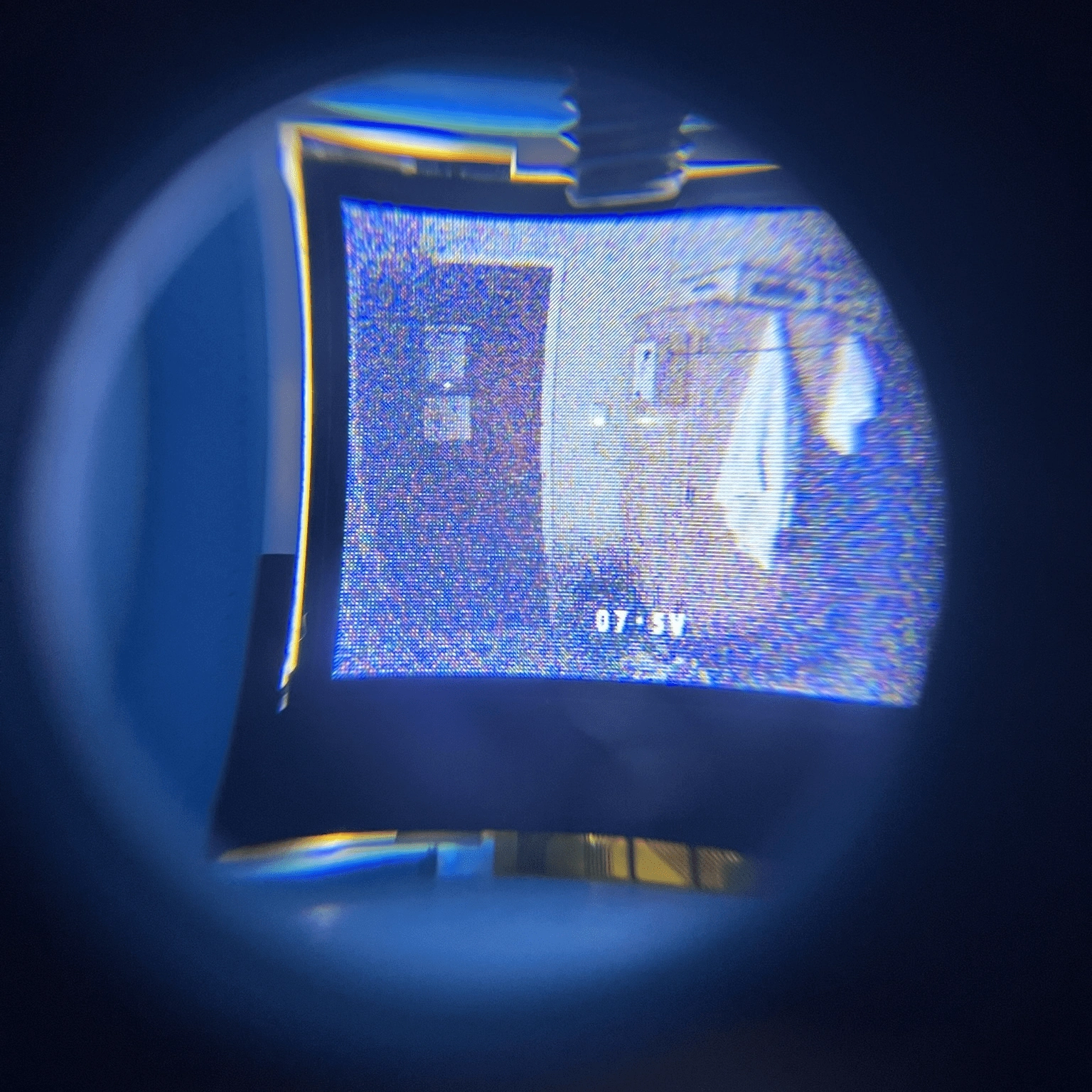
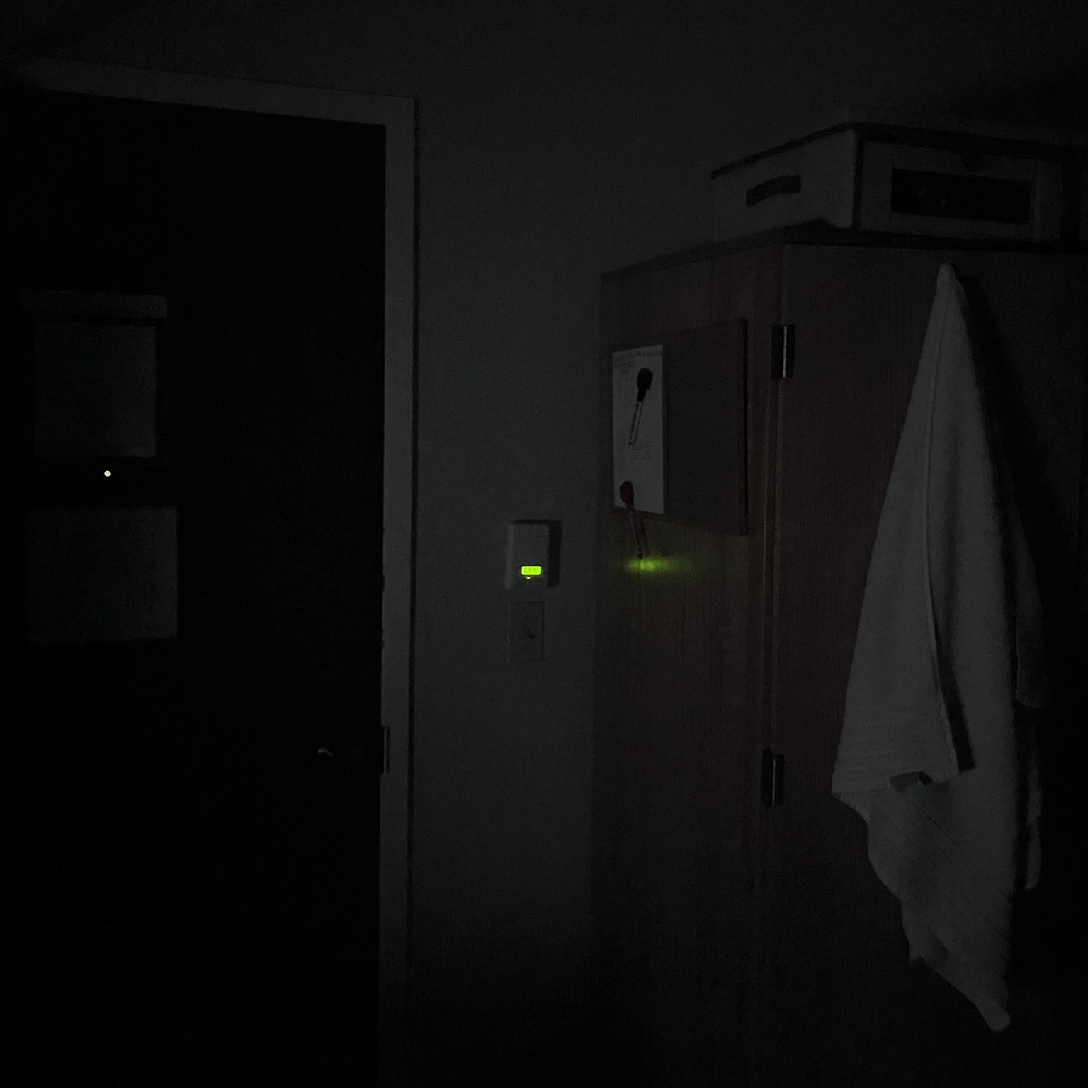
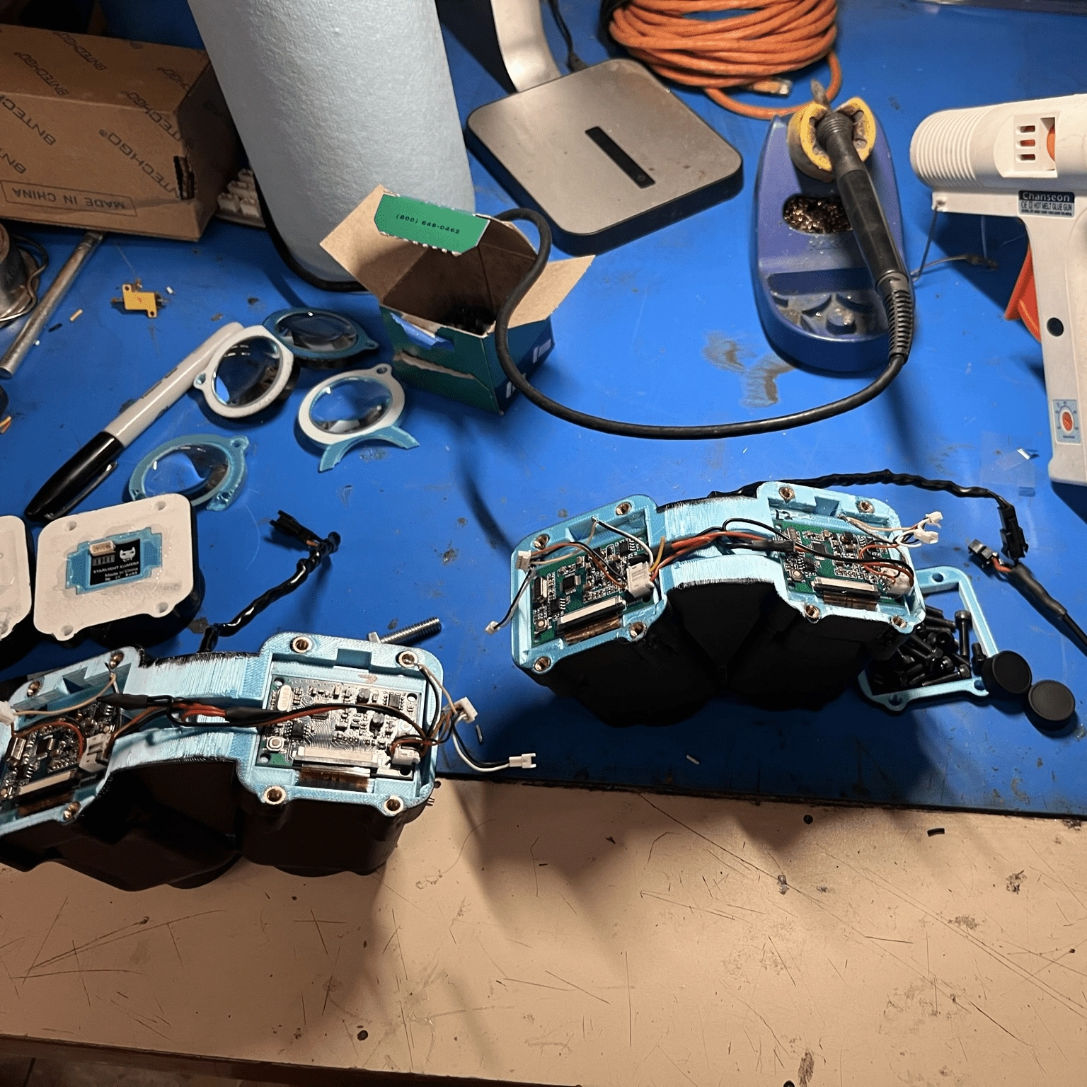
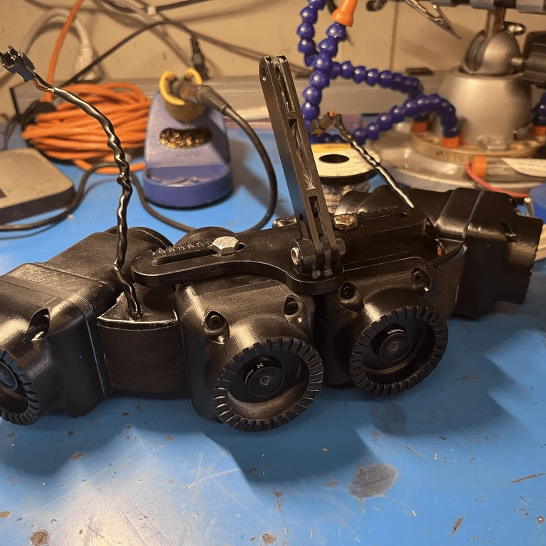
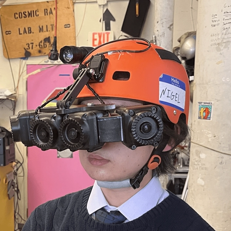
I wanted to build a fun and functional device, and thanks to ProjX funding, I had a $500 budget. This budget was perfect for building this pair (or two pairs?) of night vision goggles which I had been interested in making. Besides the cool factor, I thought they might help me traverse a dark room after my roommates go to sleep.
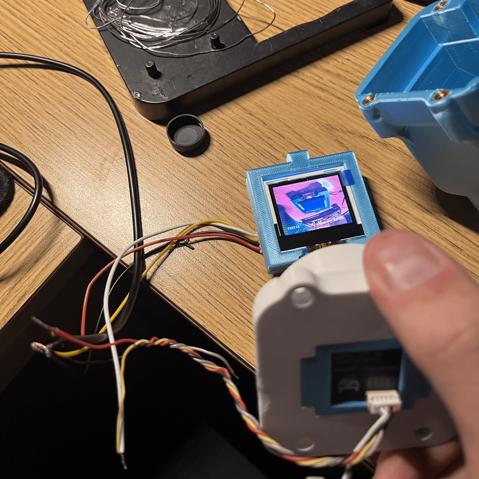
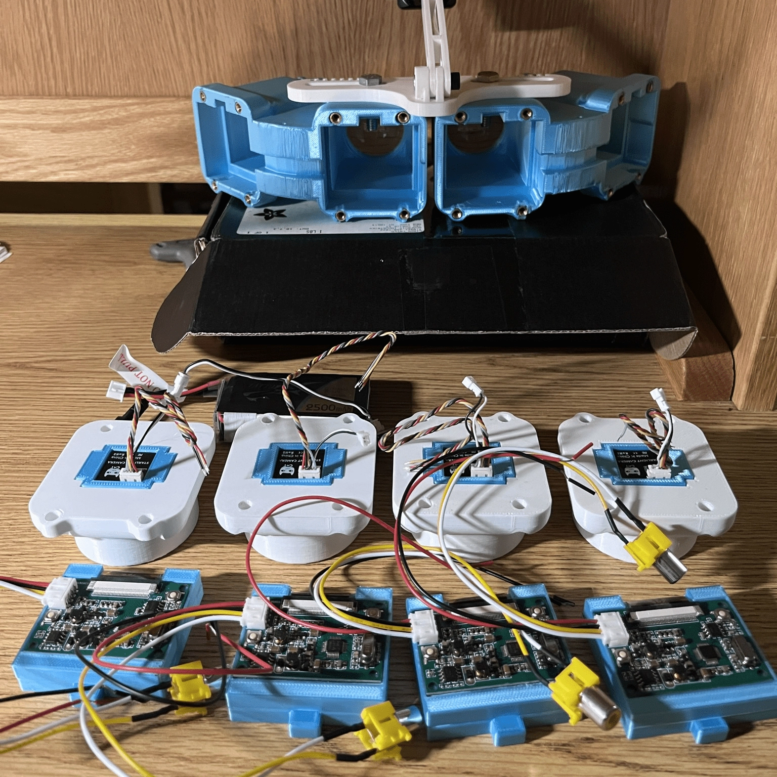
The light from the display passes through a biconvex lens. The lens corrects the picture, so the screen is clear, which is vital because the screen is too close to your eye for it to focus easily. This adjustment helps prevent eye strain caused by your eyes constantly trying to focus on the screens.
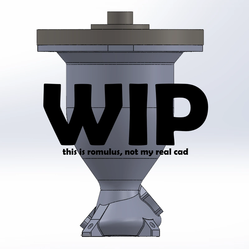
by working with my sub-team on Rocket Team to design a liquid rocket engine myself. And given the information I'm learning in 16.512 (Rocket Prop) this semester, I felt like I'd be better equipped to design an engine from first principles. I am going through the process of defining requirements, researching, and designing an engine with the intent of eventually manufacturing the design for a flight vehicle. The design is influenced by what I've worked with on Rocket Team and what I've seen accomplished by other teams and individuals.
to design a reusable bi-propellant rocket engine using LOX and RP-1, which has either film cooling or a combination of film and ablative cooling. I'm designing with a 4kN thrust requirement for 5 seconds of burn time to power a 30kg rocket.
is fairly ambitious, given my current responsibilities. Still, I hope to figure out the design work by this academic year and potentially manufacture and test next year. I also want to design the rocket, including potential custom engine control and avionics hardware and software, which would make this all a very long-term project.
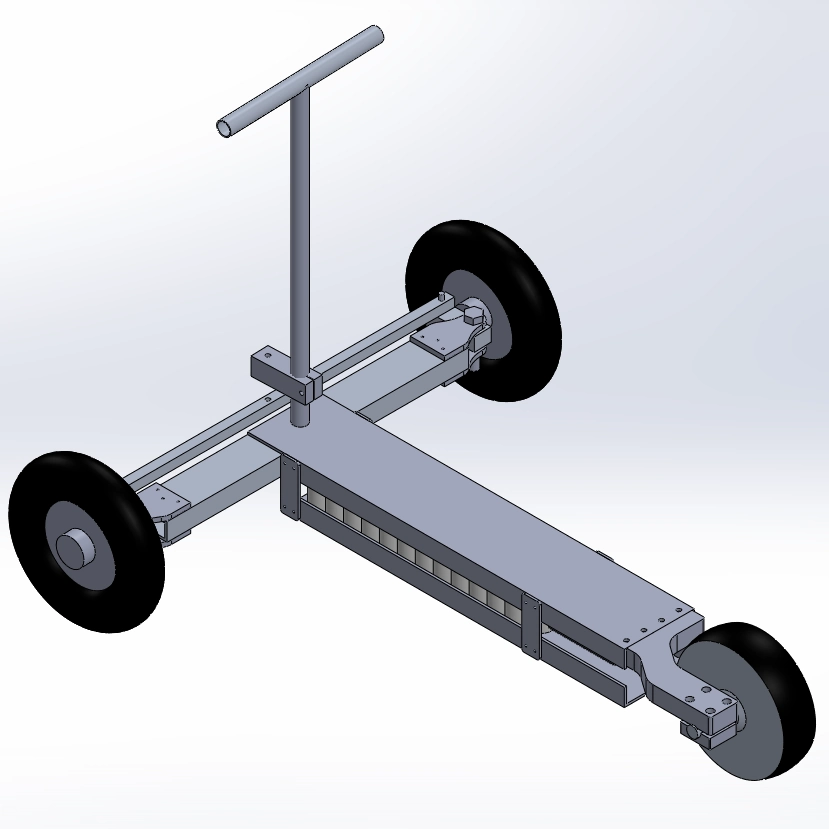
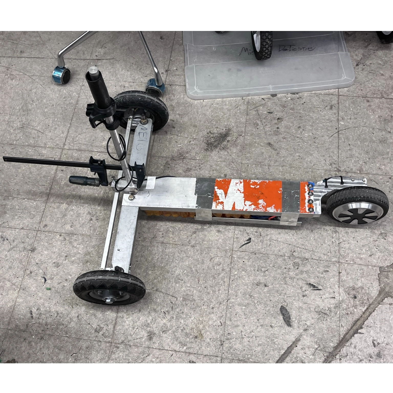
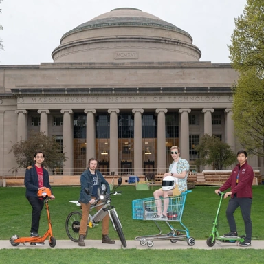
I started working on it in freshman fall after I found MITERS, but before I became a key holder to MITERS at N52-115. I had never made a scooter before, but I wanted to make my first one based on an old, small-frame reverse-tricycle scooter lying around MITERS. Knowing nothing about building a scooter, I designed a rudimentary model in SolidWorks based on the scrap available in MITERS and the old tricycle.
The first revision of the tricycle used a repurposed hoverboard motor and the hoverboard battery. The frame was made entirely of scrap lying around MITERS for maximum recycling efficiency. The wheels and throttle also came from the MITERS vehicle bins.
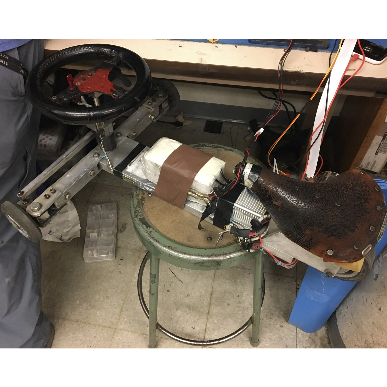
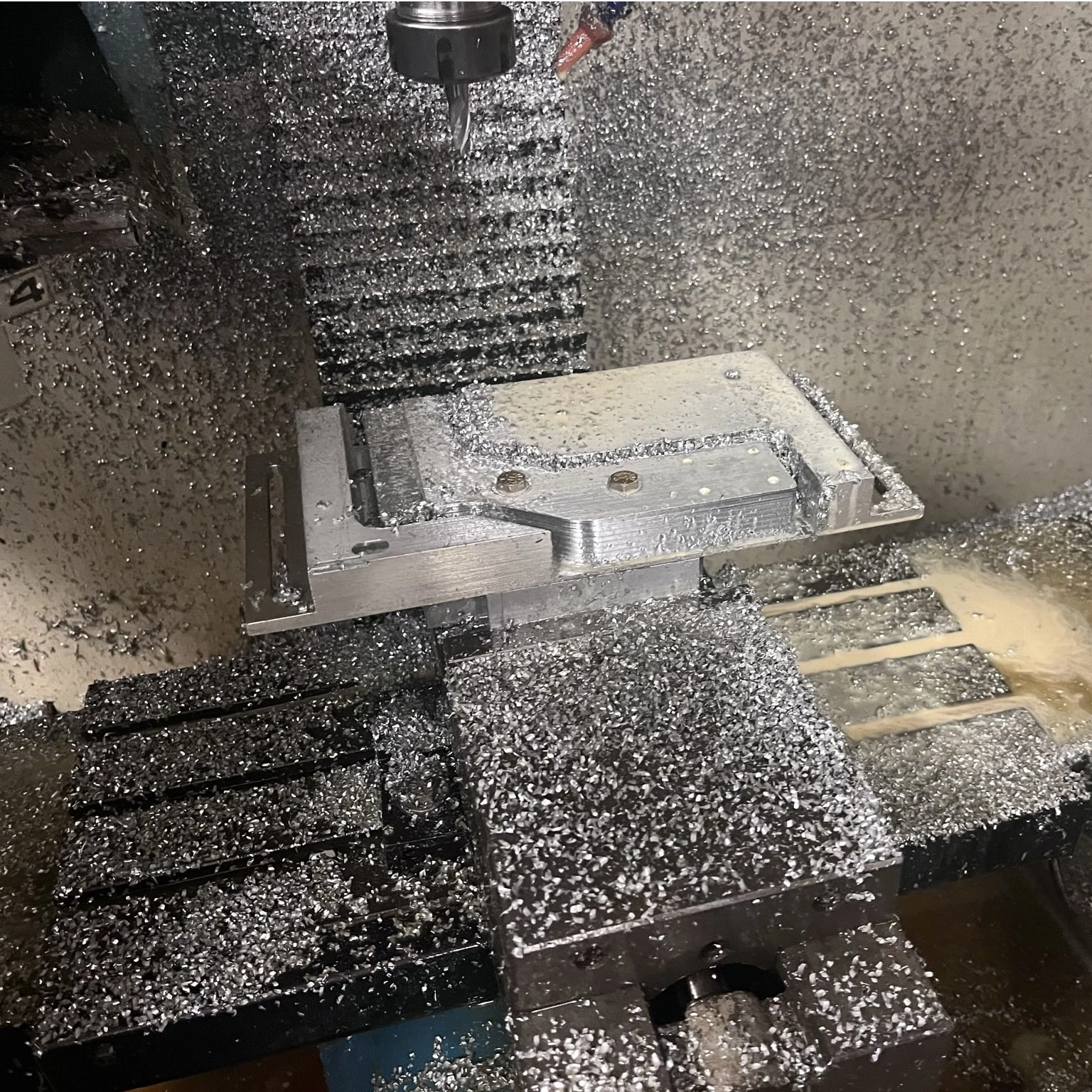
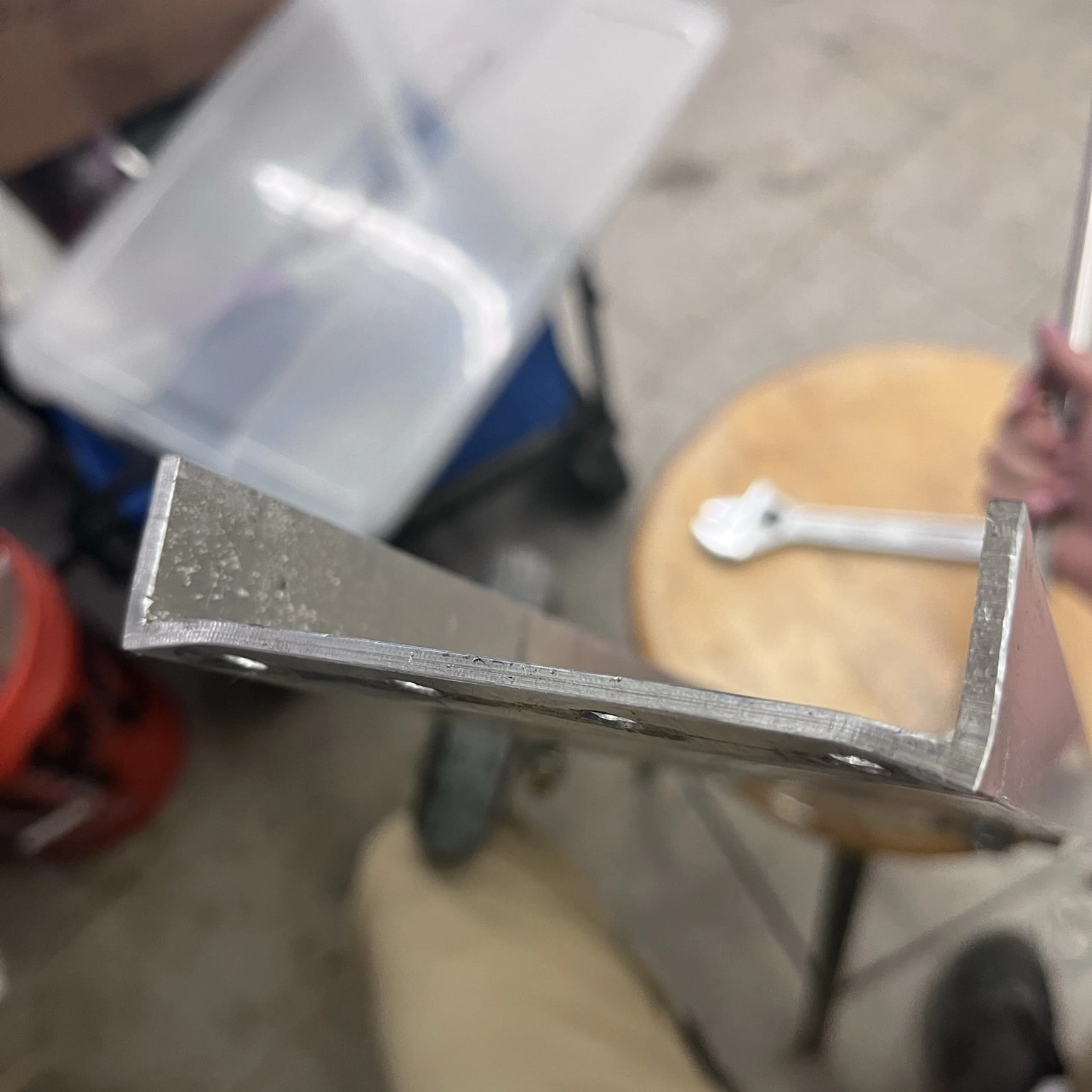
the tricycle was plagued with a handful of issues. The first was that the original way I mounted the motor was too flimsy (a recurring theme, as you will see). I had planned to cut out a section of the U-shaped aluminum extrusion I was using for the seat plate and connect the motor using a V-block and some bolts. However, the aluminum was far too thin, and the thin bar of material connecting the motor nearly bent off the first time I sat on it (I argue this was more of a design flaw than a rider issue). I remedied this problem by CNC cutting a new, much heftier motor mounting arm.
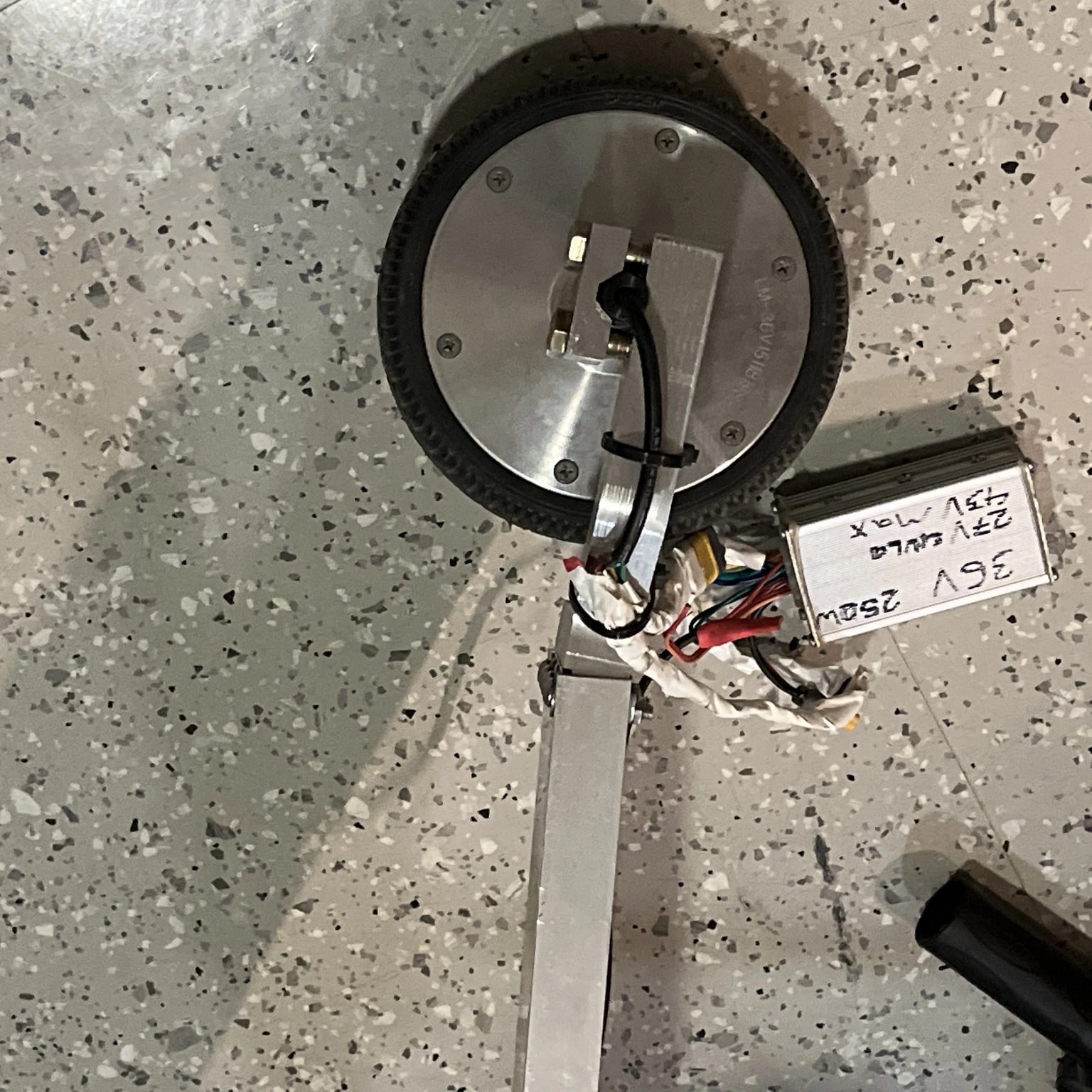
After my first few rides, the hoverboard battery died, and I couldn't charge it again. After the hoverboard battery died, I decided to make a custom battery. This wouldn't be the first time I had made a custom battery, as I had helped make the massive battery for a solar car I helped design and build in high school for a national competition. The new battery was made of 12 lithium-iron phosphate batteries in a series by four in parallel (12S4P) for a 40V nominal charge, capable of overvolting the hoverboard motor.
Somewhere along the way, the flimsily attached handlebar (see picture three) snapped off, leading me to improvise with a shop clamp (or my hands on the connecting block) to steer the tricycle effectively.
And as it turned out, the super beefy motor arm I had made was somewhat of an overcompensation for my past design flaws. The mount was so hefty that the frame broke around the arm, leading to the deformation on the U-extrusion seen in pictures nine and ten.
There's definitely more work I need to do to make the tricycle fully functional. Still, I decided to stop working on it pending a new redesign. And the likelihood of the need to buy dedicated parts and materials for a redesign makes this project more unlikely to continue. I learned a lot from this project which I would later put into building my scooter.
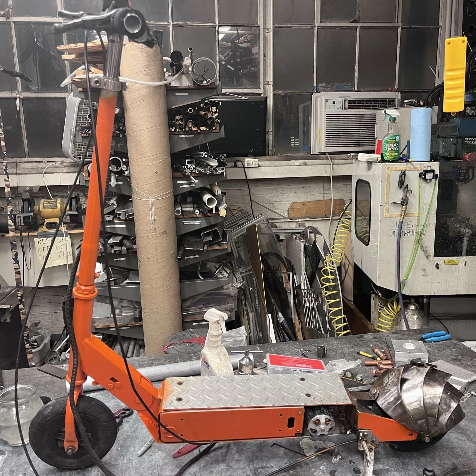
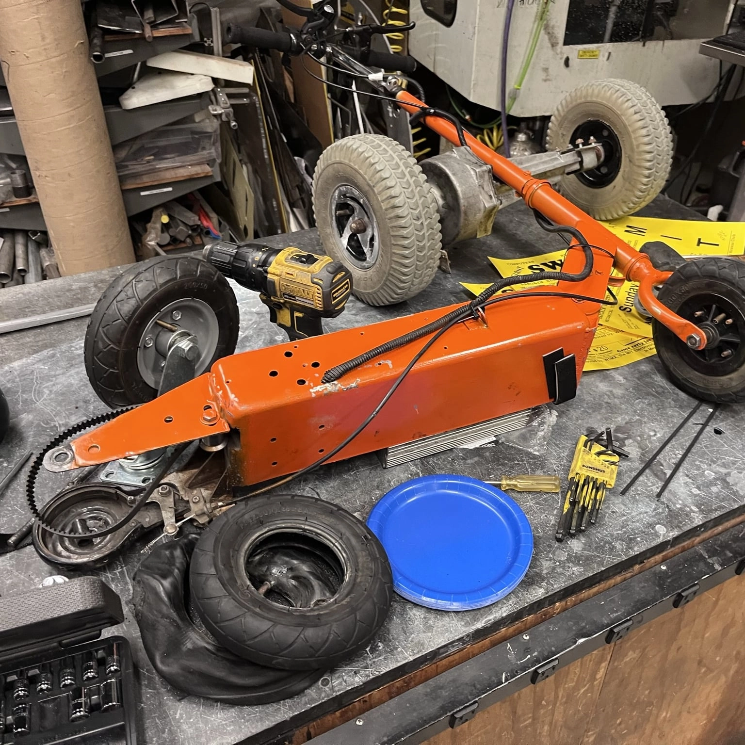
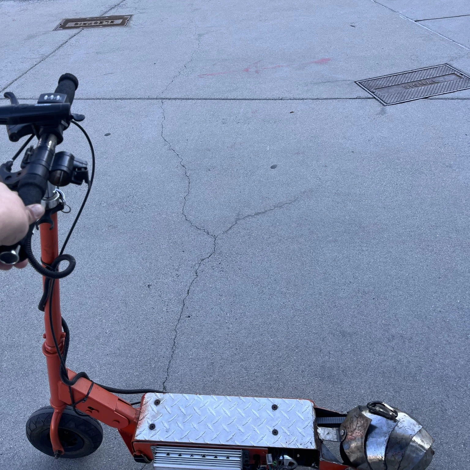
I had a better start compared to the tricycle. Based on how difficult it was to make the tricycle work, I started by refurbishing and revitalizing an older vehicle of MITERS instead of designing one from scratch. The scooter was owned by previous MITERS member and president Mason Massie. By some means, the old battery combusted while inside the scooter body. Thankfully, the battery compartment of the scooter's steel frame was the only part horrifically charred and gross. So after cleaning out the internals and removing some external rust with a wire brush and flap sander, I had a scooter frame with handlebars, wheels, and motor already mounted.
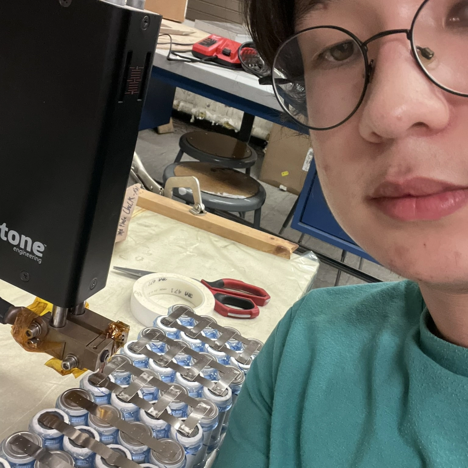
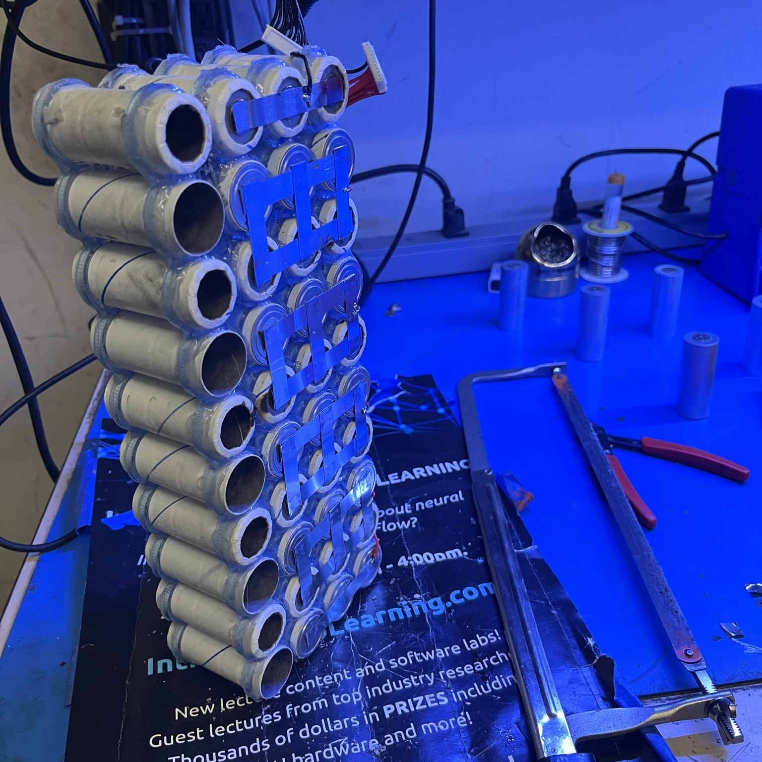
to make the scooter run again was to build a new battery. Taking what I learned from the first pack I made for the tricycle, I made a frame out of a laser-cut acrylic sheet to support the battery cells better. While this wasn't as good as an off-the-shelf solution and still required some structural hot glue for rigidity, this pack felt more solid than the first. I used the N51 spot welder instead of a handheld unit to attach the same lithium-iron phosphate batteries in a ten series and four parallel (12S4P) configuration. After I attached the battery management system (BMS) to the pack, I was done (or so I thought). After finishing the battery pack, I painted the frame for rust protection and, most importantly, aesthetics in my favorite color: orange.
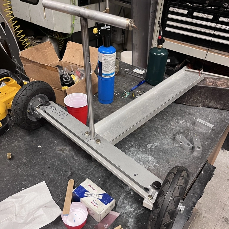
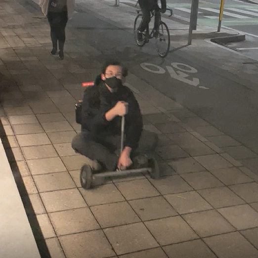
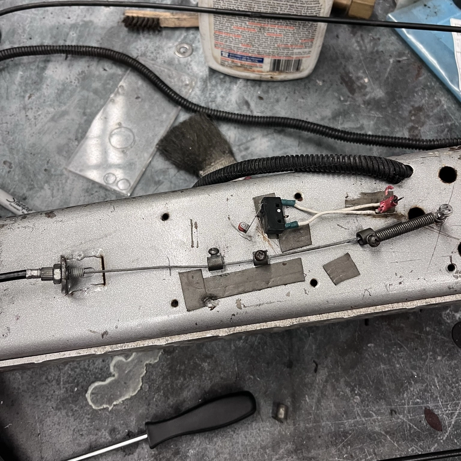
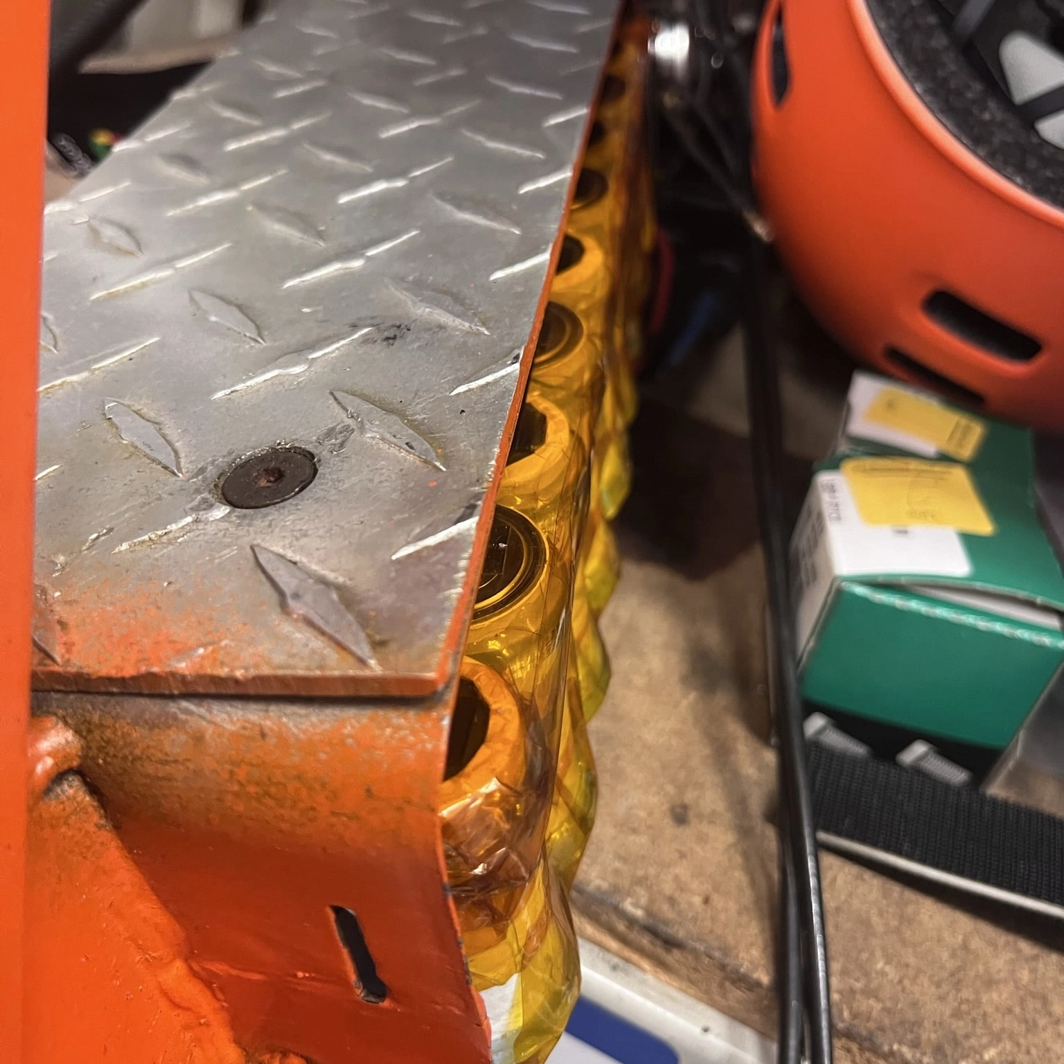
set by my tricycle project, problems started at the halfway-ish point of my scooter refurbishment. It turned out that sitting on a rack for the entirety of quarantine (and probably longer) wasn't great for the cheap scooter tires on the frame, so I had to replace the rear tire. After that, which you can see in photo six, the battery was somehow TOO BIG. I figured out that the added spacing from the battery frame and wiring made the pack too large. For the record, I had fit-checked the four cells beforehand. I was somewhat at my wit's end between the difficulties I had making the battery pack and all the other school things going on, so I took a hiatus from the project.
(or hacksaw job, ha ha) solution to the problem was to cut off a row of series cells, making the pack 10S and 3P. While lopping off ten cells reduced the capacity, the pack now fit into the battery compartment, and I could ride the scooter for the first time. While I could travel to the edges of campus comfortably, I constantly had to charge the battery with a modified off-the-shelf wall charger to ensure I wouldn't have to walk back. Because of this, I decided to make a new battery pack.
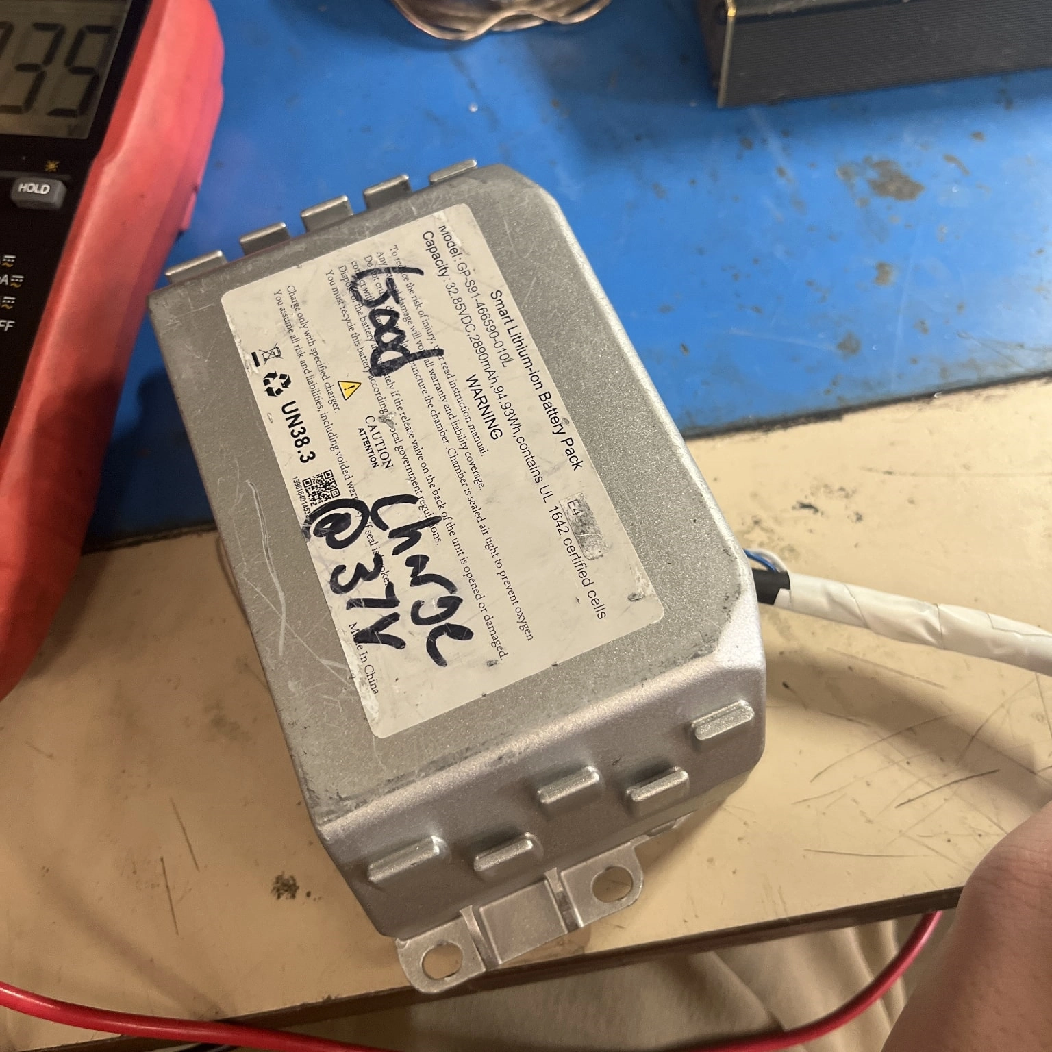
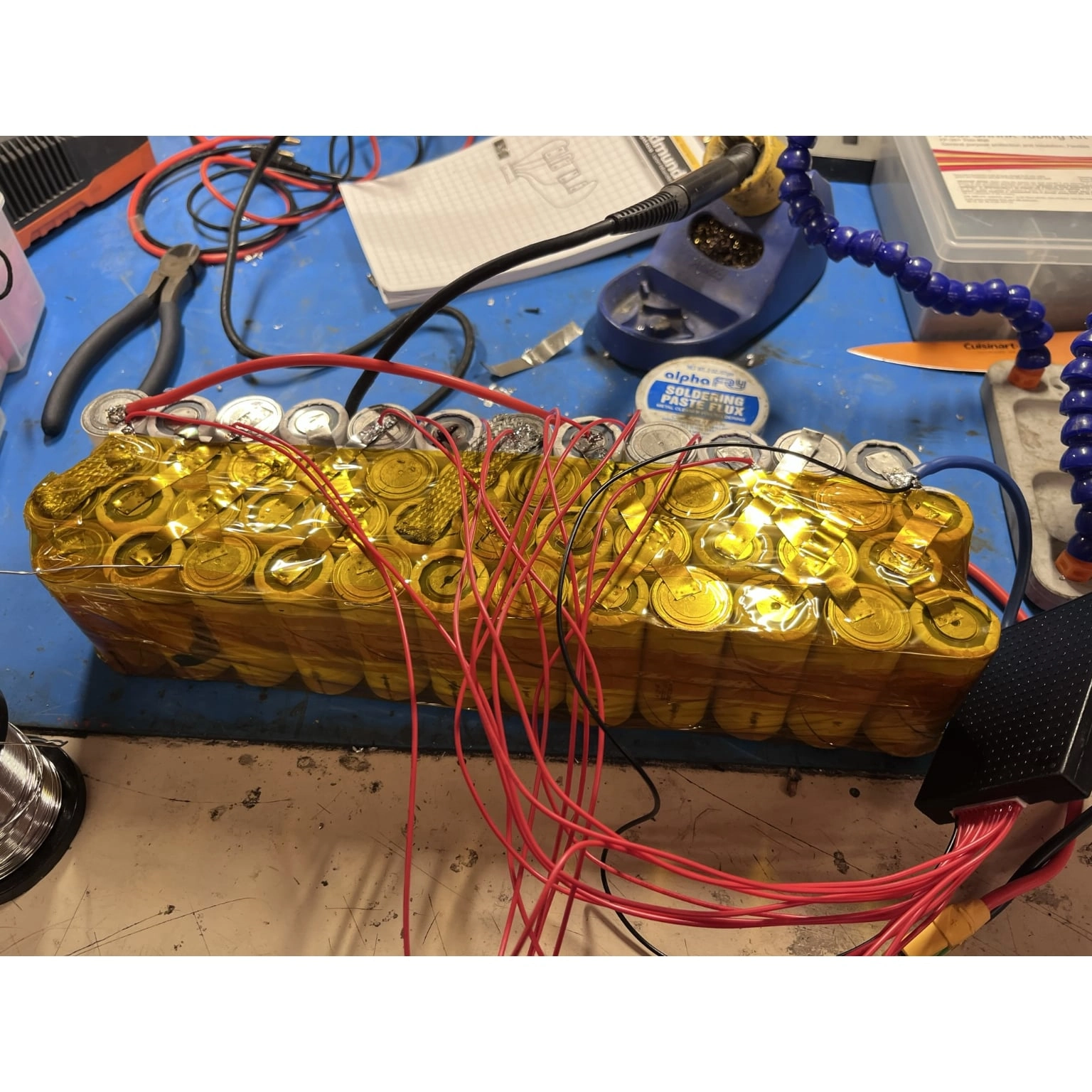
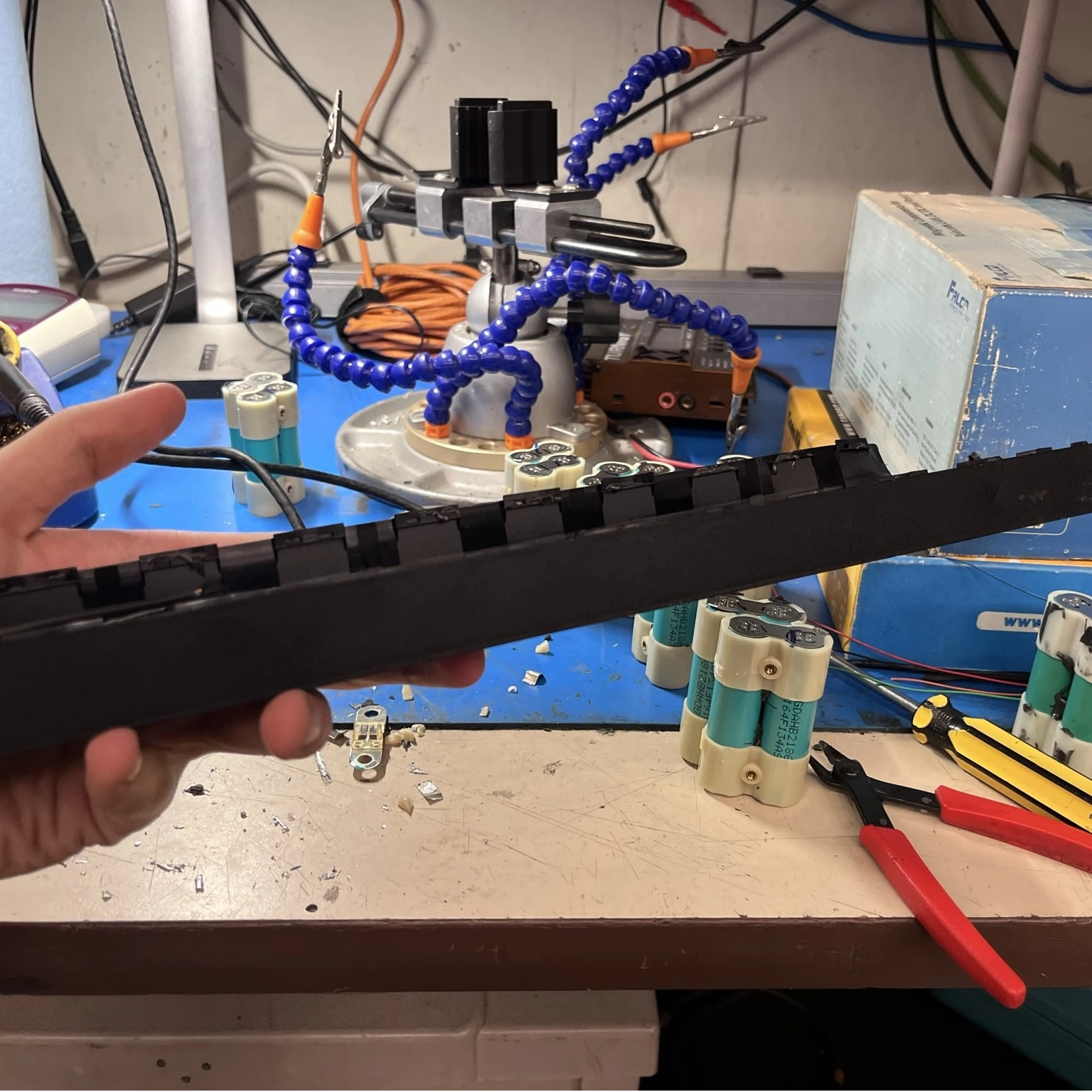
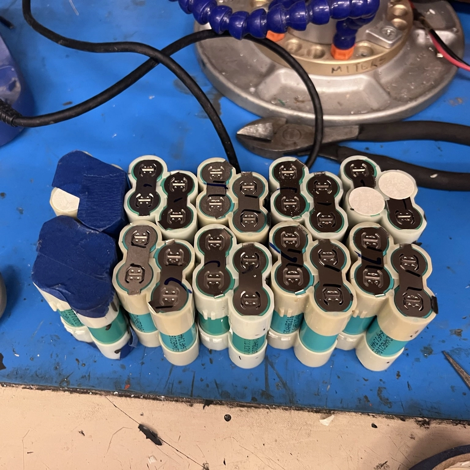
Joseph, another MITERS member, generously gifted me three UPS battery modules he had crufted. These modules contained four bundles of four 18650 battery cells, meaning I had 48 18650 batteries to work with. Well, it was actually only 40 because I screwed up two cell packs when I salvaged the batteries. So I now had a 40-cell, 10S 4P battery pack which was smaller and theoretically higher capacity than my previous battery pack. I spot-welded the battery before leaving for summer 2022 but did not attach a BMS.
I came back in the fall of 2022 to complete the battery pack and make the scooter functional again. I tested the battery to make sure it was okay after sitting around all summer, and to my dismay, one of the rows of cells was almost 2 volts lower than the rest. This meant that there was some problem with the battery pack. After slowly charging the row to balance the battery pack manually, I tried charging the battery from a bench power supply. Immediately after I turned on the power supply, the nickel strips connecting the cells turned red hot, meaning something was seriously wrong with my pack.
I've decided to stop this project because I don't want to buy new cells for a new battery, and I've moved away from scooters. I realized that building a high-power vehicle like this wasn't moving in a safe direction.
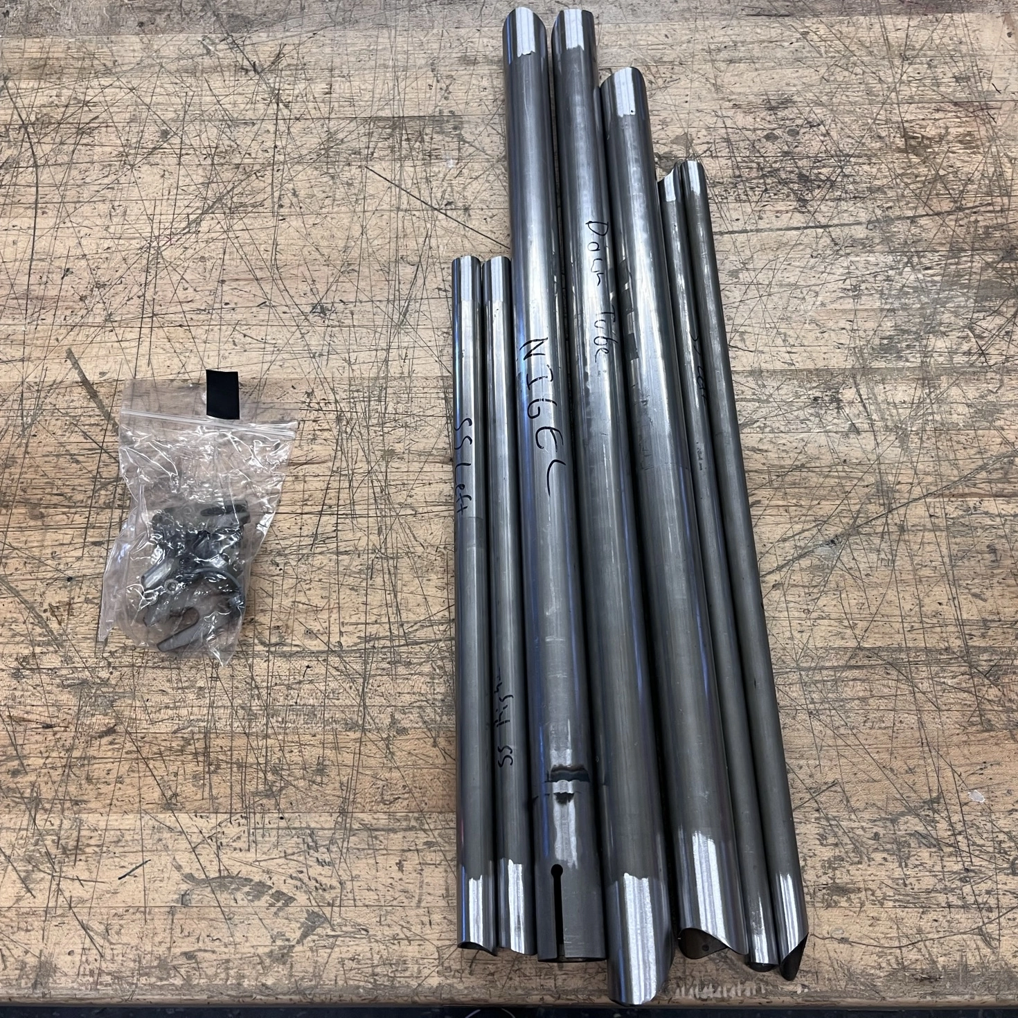
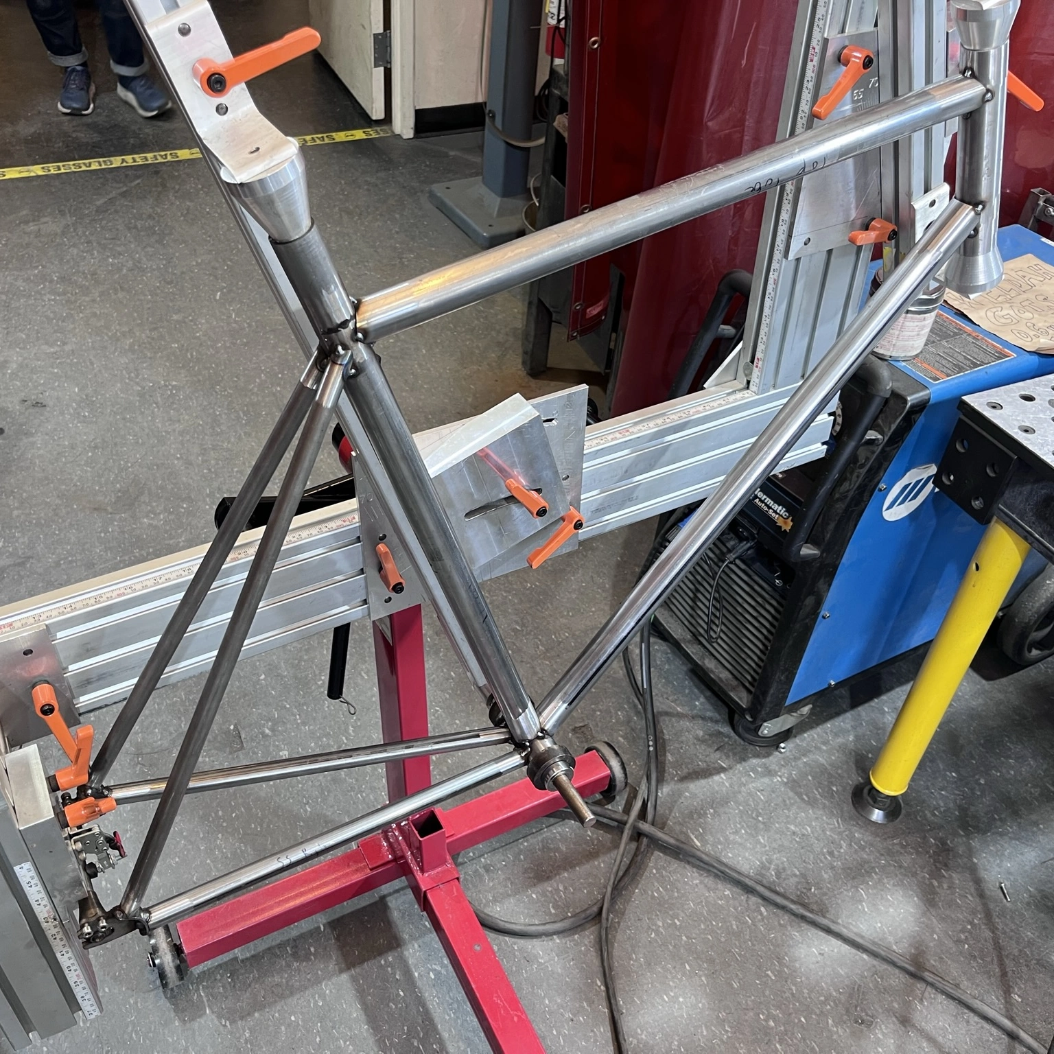
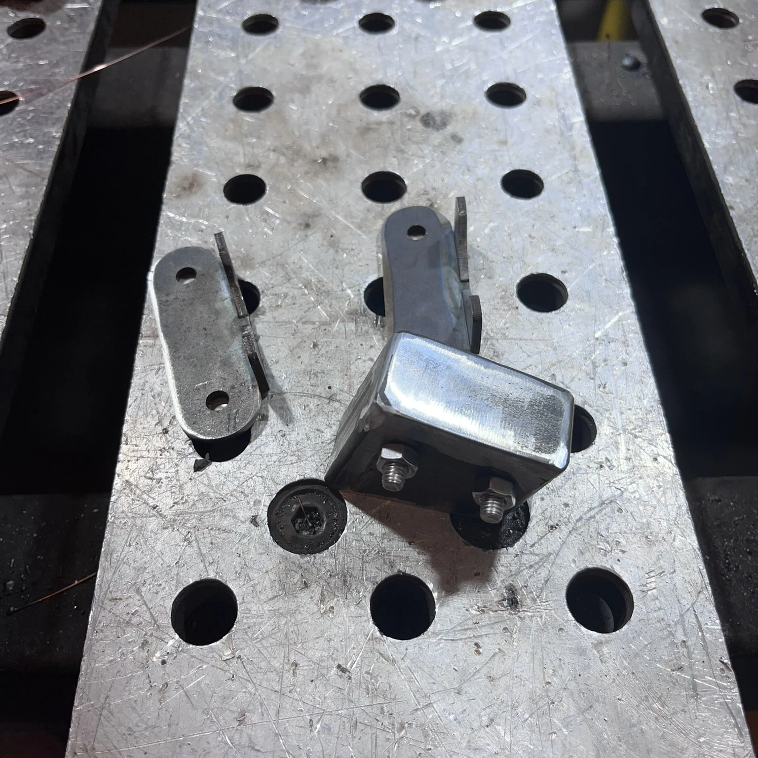
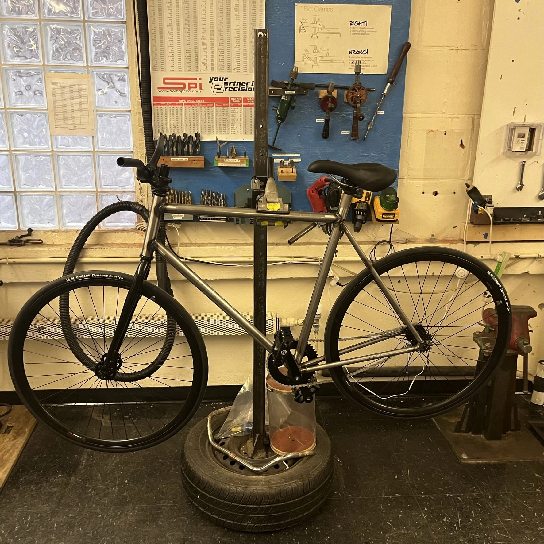
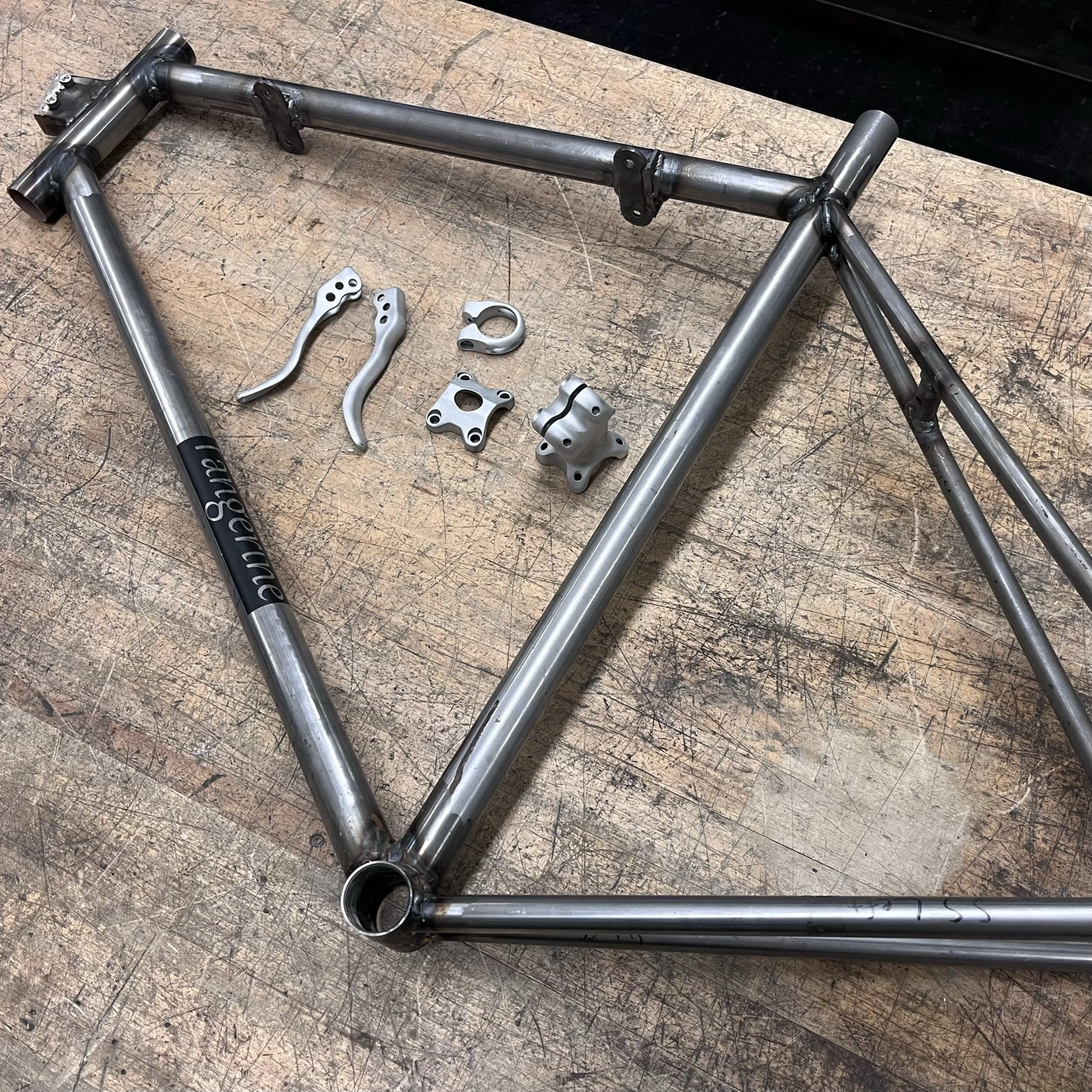
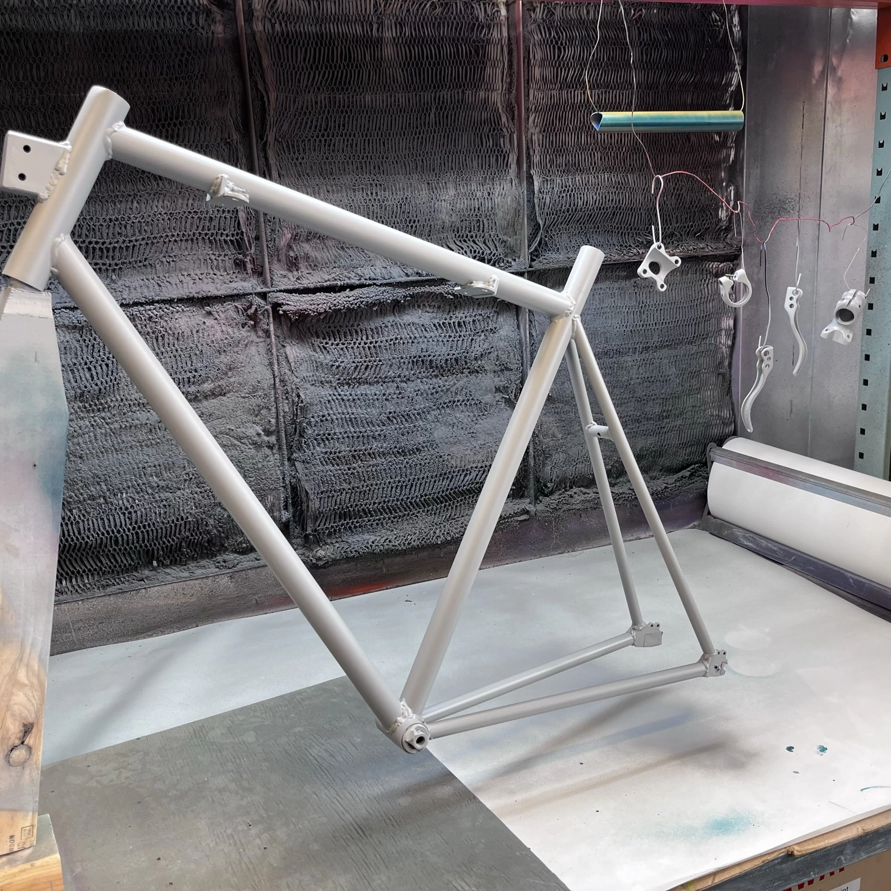
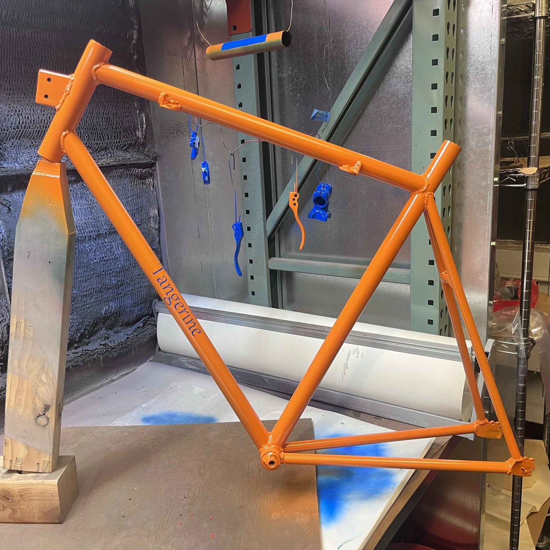
I built during IAP 2023 through the D-Lab class EC.S02 taught by the esteemed Jack Whipple. It's a single-speed road bike with an emphasis on modularity. While the bike was only supposed to take a few days of work to complete, I added lots of details and tweaks to the class design that made the project more fun but also more complex to complete. The steps I took in roughly chronological order are the following:
Thirteen steps doesn't sound so bad for such a good end product, but in reality, there are actually three to ten sub-steps to each step.
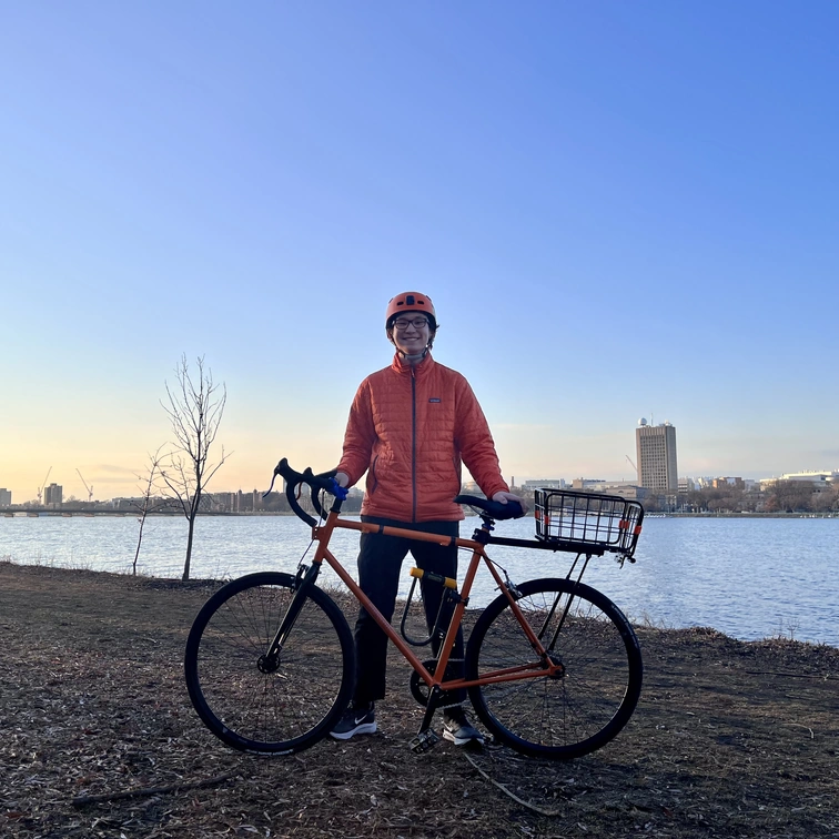
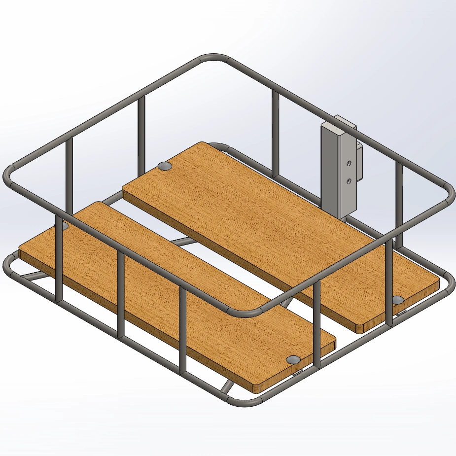
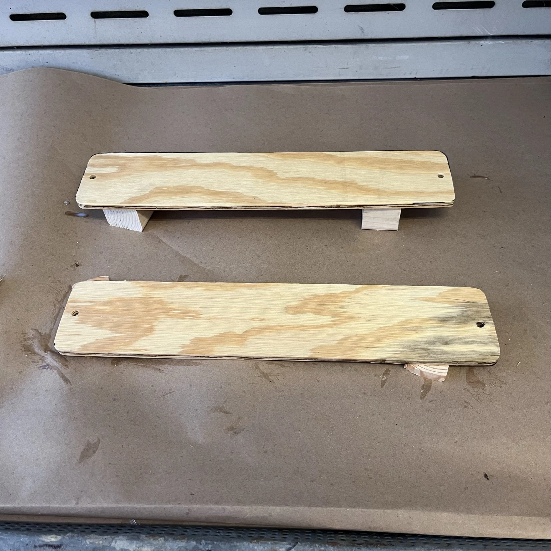
Overall, I'm pleased with how Tangerine turned out. There are a few bad welds and already some nicks in the paint, but I did an excellent job for my first bike. The riding feeling is also fairly smooth, but my perception may be somewhat skewed since I haven't ridden a bike seriously in a while. As for the basket, I've made a design but have yet to finish it since I already have a back rack that is sufficient to hold my backpack or my groceries.
I'm excited to ride Tangerine more and all the places we'll go to in the future. I'm also considering electrifying Tangerine using the mounting brackets I welded during the initial construction. I found a front wheel hub motor and have done some research on potential battery packs.
4.52 mi (7.27 km)
and Spring semester of 2023 (Jan-May), I was helping out in the MIT Space Propulsion Lab (SPL) as a continuation of my UROP work that I've been doing since Jan. 2022. For this more recent work, I was helping to refine the method that SPL uses to coat the special electrowetting valves used in their electrospray ion thrusters. The information is technically proprietary, so to respect that, I'll give a brief overview of my work.
as a UROP summary in the spring 2023 MIT Undergraduate Research Journal (vol. 45). Check it out here on page 27: MURJ.
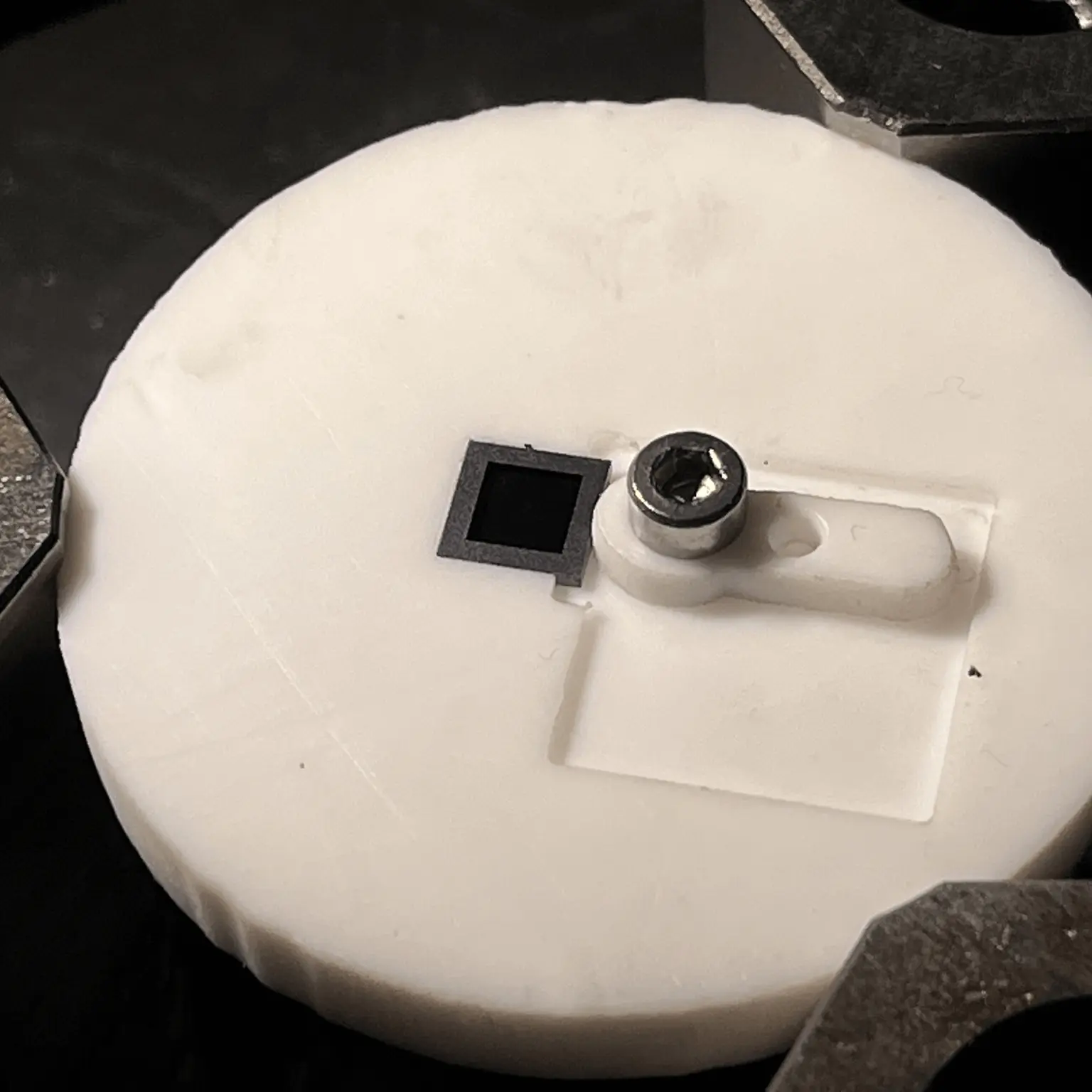
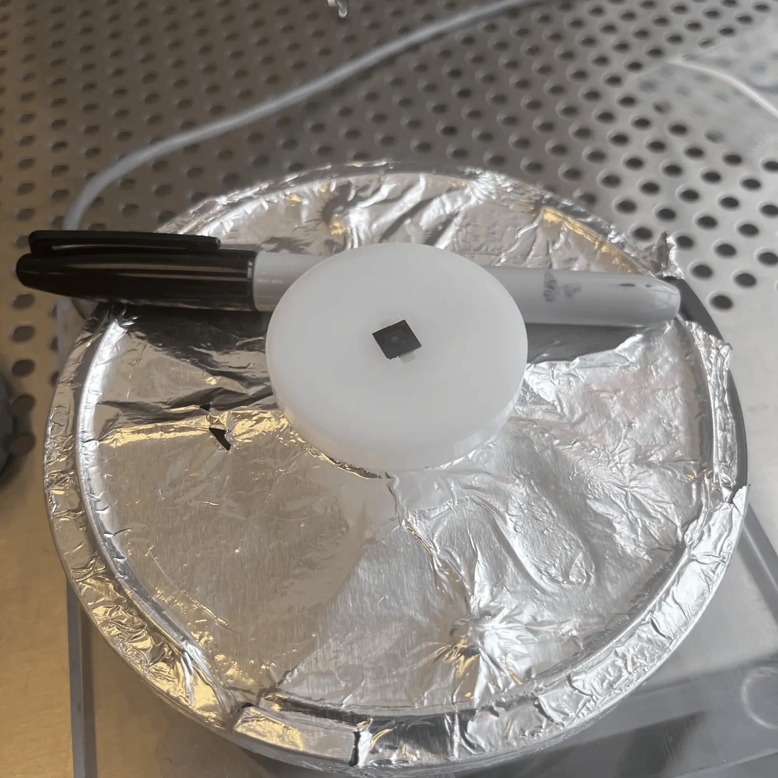
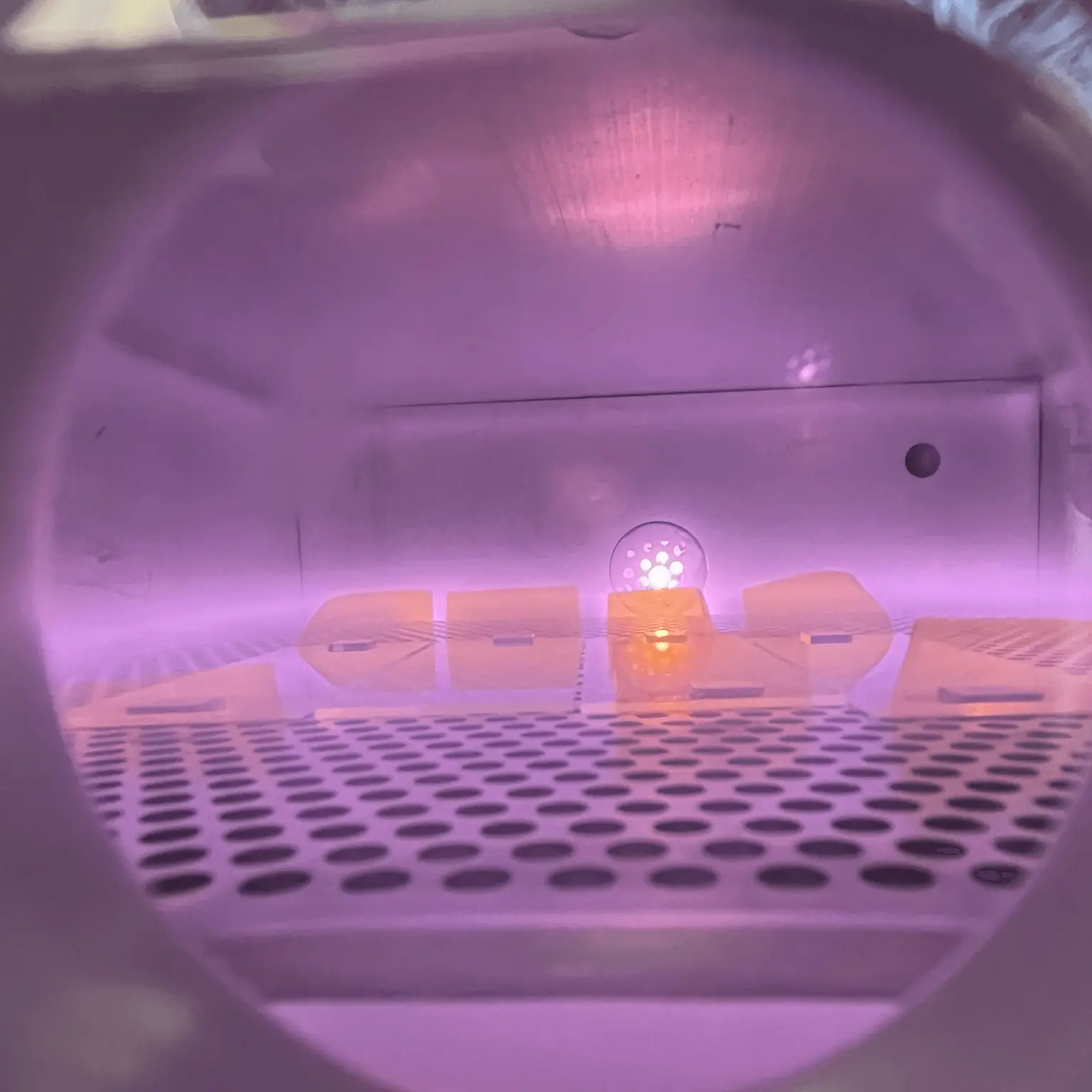
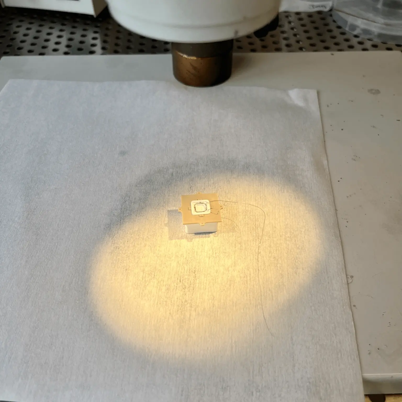
design and fabricate a new jig (photos 2 & 3) for the spin coating process SPL uses to coat the valves. The spin coating setup ensures that a thin layer of a chemical, FluoroPel, is deposited on the active surface of the valve.
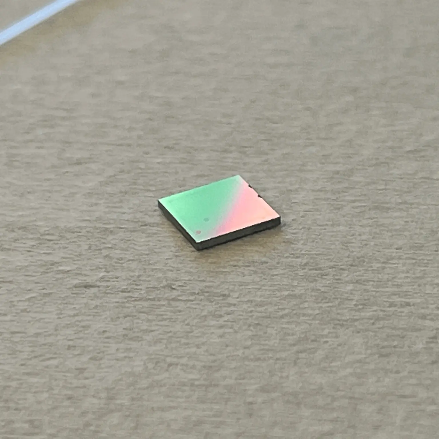
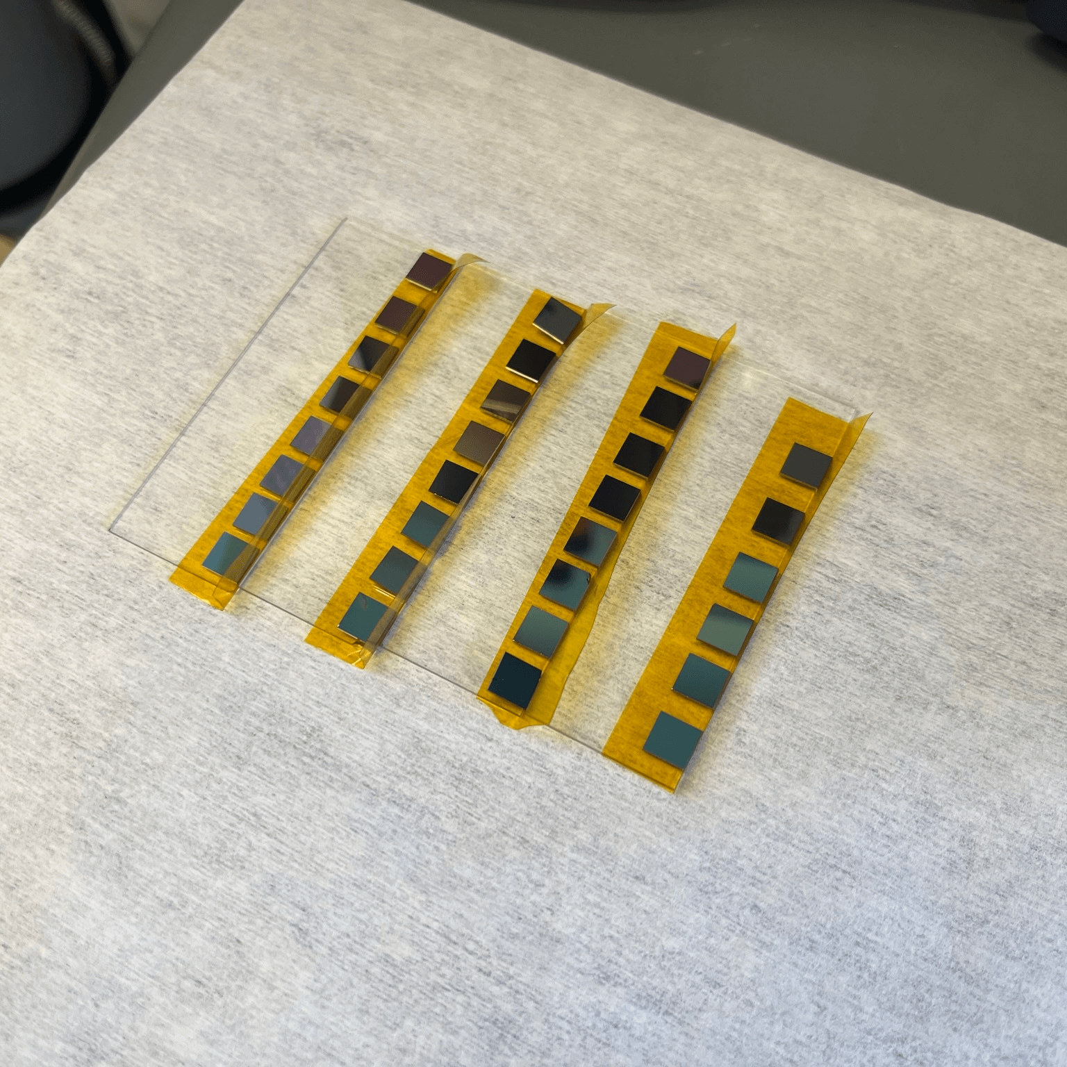
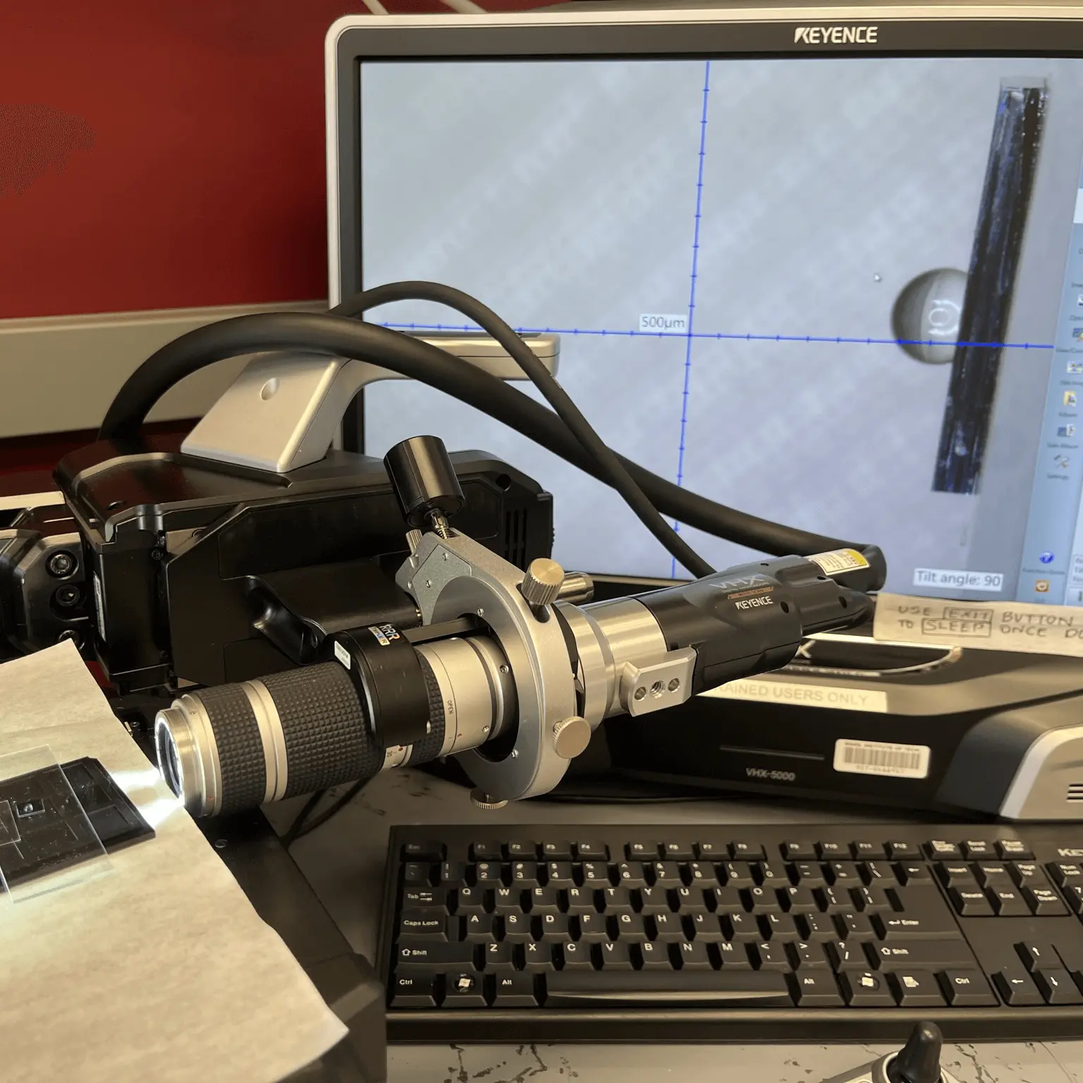
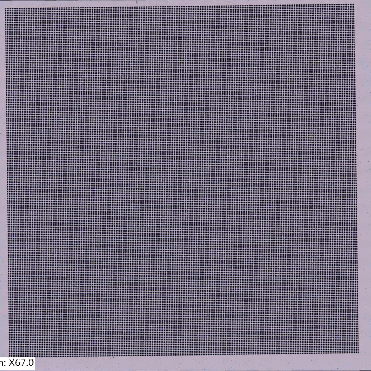
they're these silicon chips (MEMS) with hundreds of tiny capillaries microns in diameter in a square pattern (Photo 10), and we coat them in a particular chemical called FluoroPel. Once cured onto the silicon valves, the FluoroPel increases the hydrophobicity of the valve's surface, meaning that the fuel for the thruster, the ionic liquid, cannot pass through the tiny capillaries going through the valve. It comes down to how the fluid interacts with the surface of the valve, but a higher contact angle (what I'm measuring in photo 8) is better.
unique properties of FluoroPel, if we apply a voltage across the ionic liquid and the valve, we can change the interaction between the valve and the thruster fuel. This change from electricity is what makes the valves electrowetting. The electrowetting property of the valve then allows someone controlling the satellite to turn on the thruster by applying a voltage to the valve and allowing the ionic liquid fuel to reach the electrospray thruster.
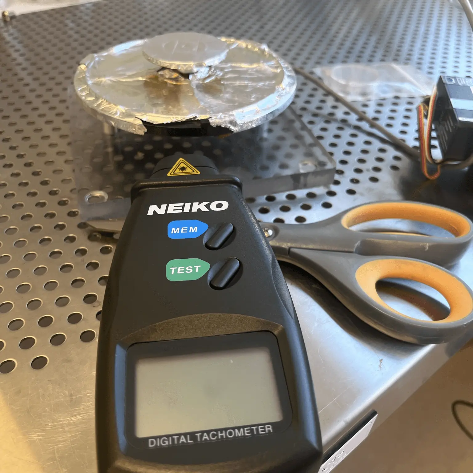
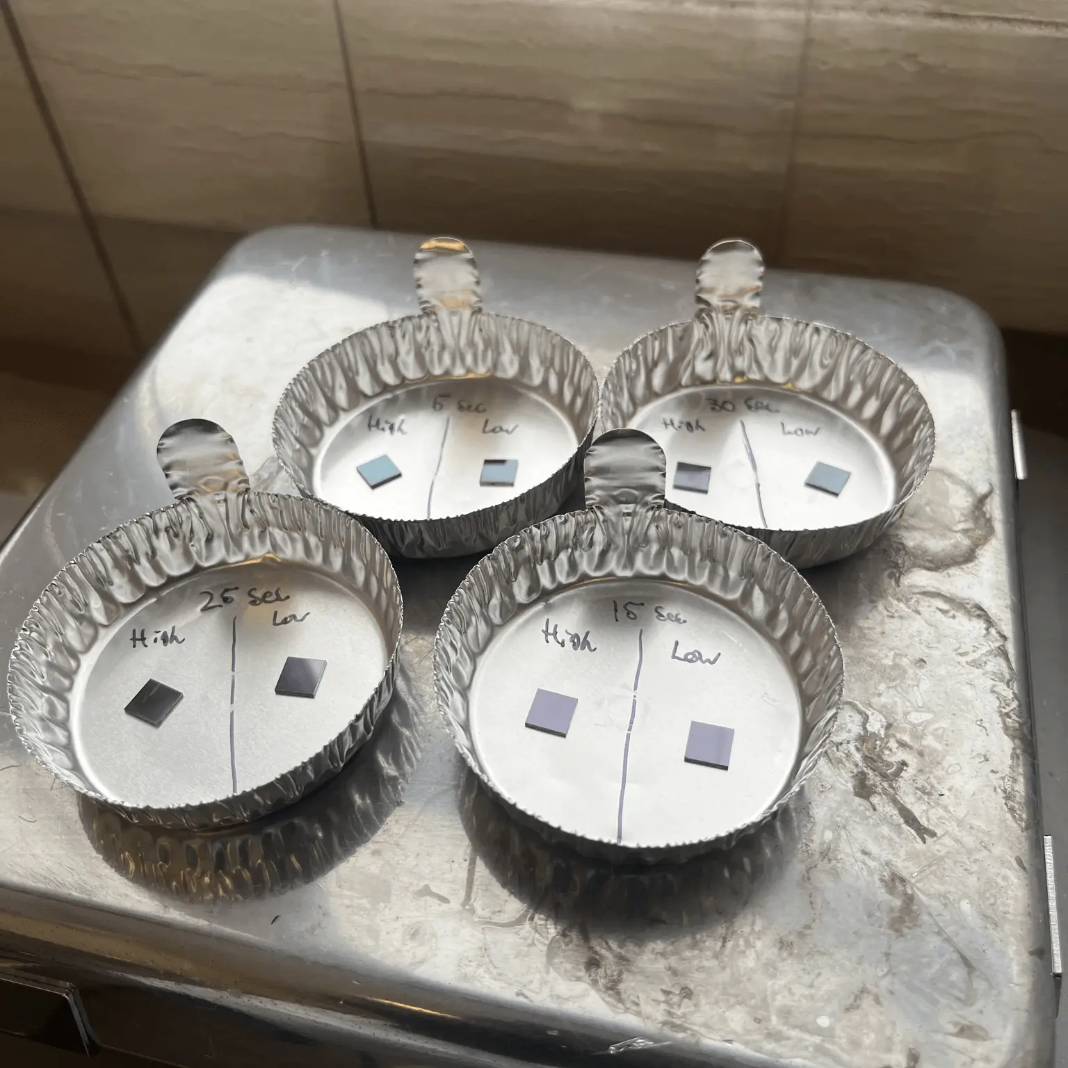
the new spin coating jig, I then worked to optimize the spin coating procedure SPL was using to find the spin coating settings that produced the largest contact angle. A larger contact angle is preferable since the angle size correlates to how reliable the valve is in preventing ionic liquid from traveling through the thruster. So basically, I was going through the rigorous cleaning and coating process for 34 valves and took over 354 contact angle images to accurately characterize what speed and process was optimal to coat a valve. The intent is that SPL can use the information I gathered this semester to produce the valves needed for the next important mission: STEP-1.
this UROP project was to test one of the valves coated to the optimized procedure in environmental conditions to see whether or not the valve would prevent the thruster from failing during a spacecraft launch. Unfortunately, since there were a few blocks to this and it was the end of the semester, I couldn't certify a valve experimentally. But I'm still looking forward to working with SPL in future semesters for other UROP projects.
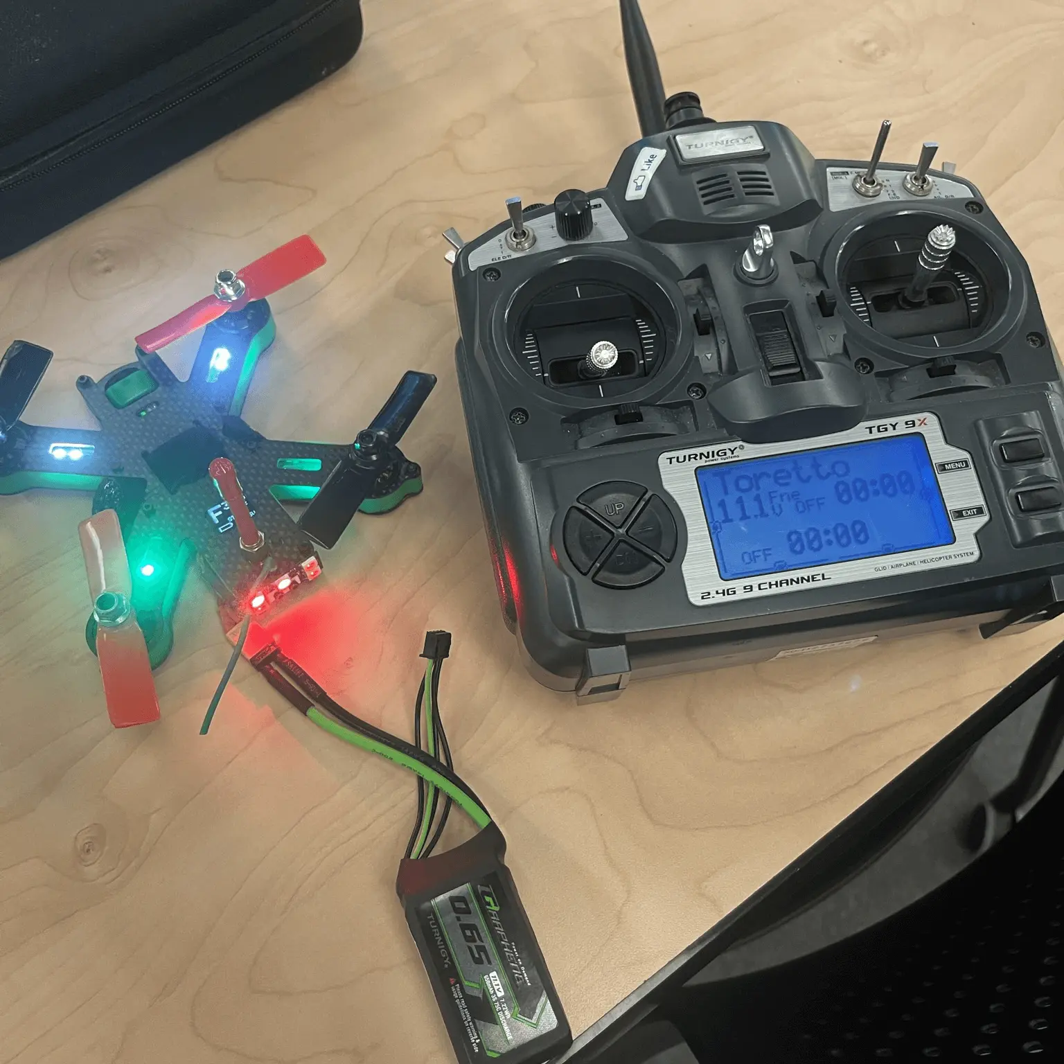
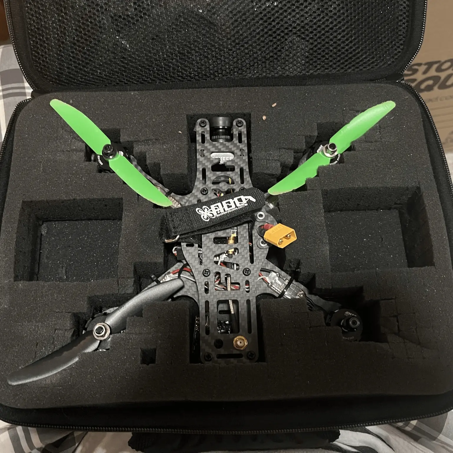
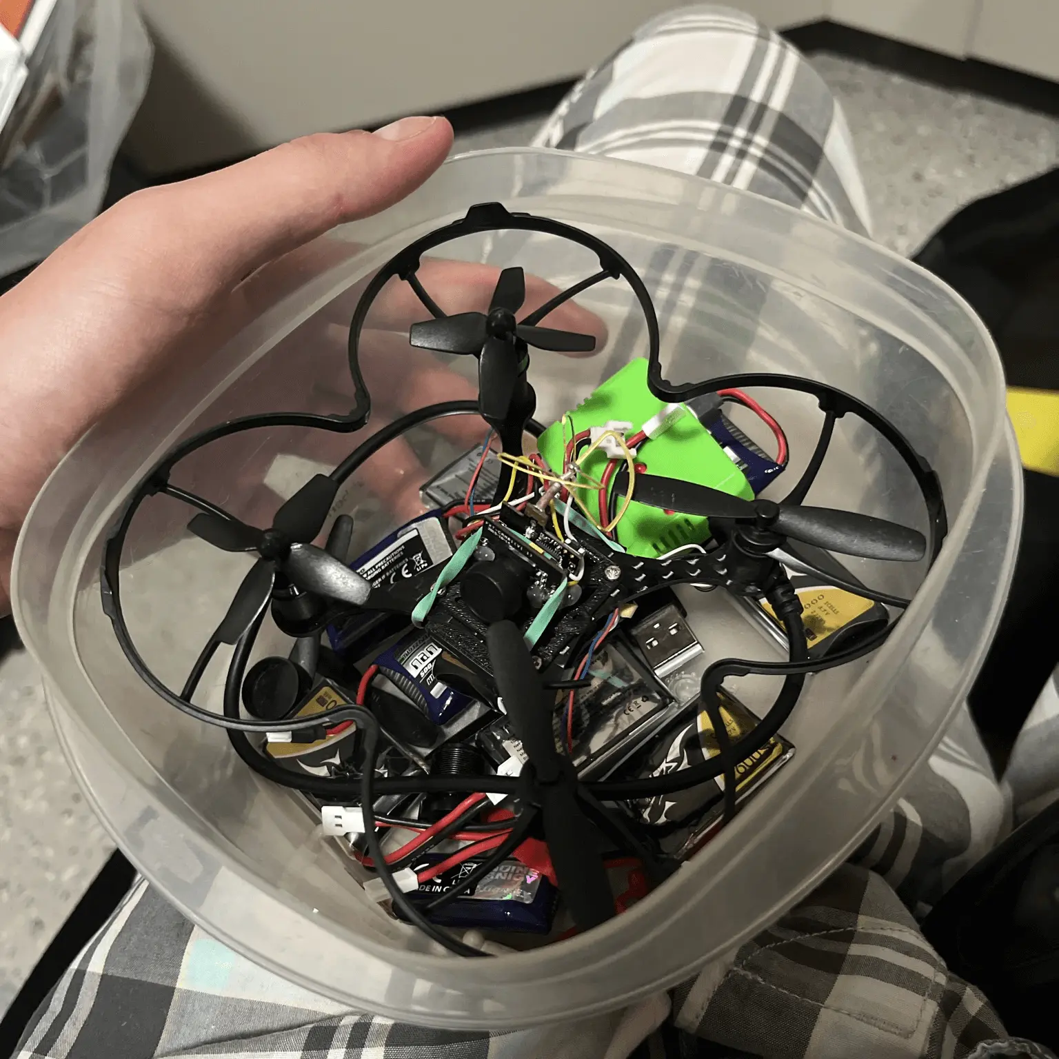
I was generously gifted some FPC drones and related equipment from an MIT alumni. It was a bag of props, a few drones, a goggle set, and a transmitter. Since I got it, I've flown the Toretto a few times with limited success before schwacking (the technical term) the antenna, making both medium-sized drones nonfunctional. In addition, the 5” quad needs a new transceiver entirely. I'm looking into finding a replacement antenna for the Toretto, but it's difficult to source components since these have been mostly discontinued products.
I'm looking forward to learning more about these FPV drones, repairing them, learning how to fly them properly, and hopefully getting some cool footage and fly time around campus and/or my local area in Washington.
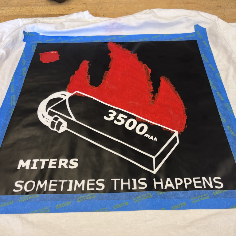
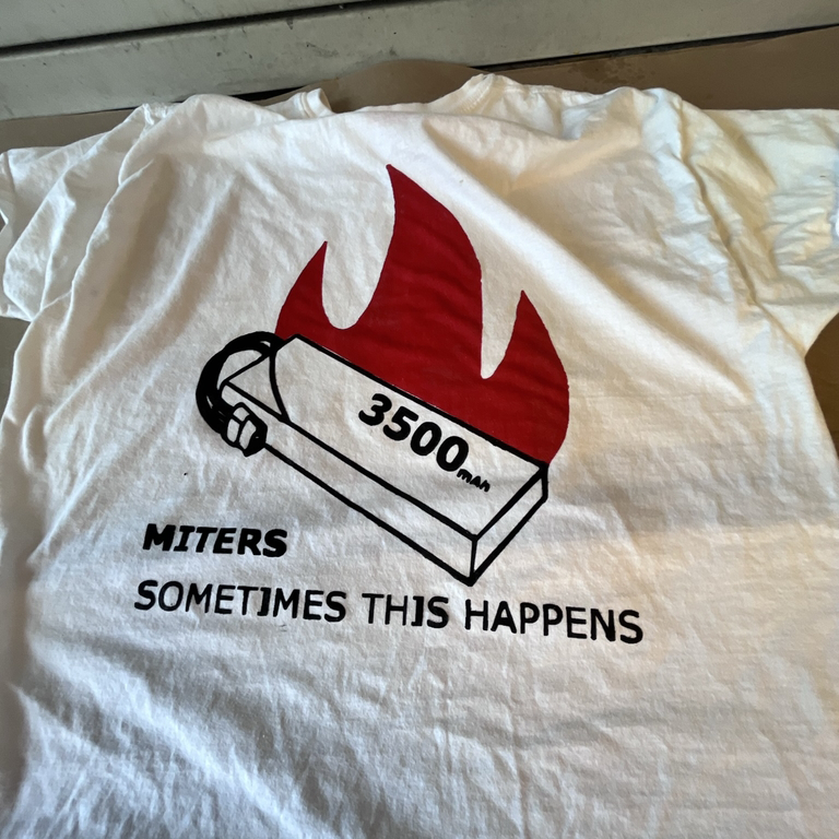
the esteemed Jack Whipple. introduced me to the resources in the MIT DesignPlus makerspace. One of their machines is a 2D electronic cutting machine which I used to cut vinyl stickers and stencils. I first made a double-sided, two-colored MITERS battery fire t-shirt.
motivated me to learn essential aspects of Adobe Illustrator. Illustrator allowed me to efficiently create designs I could cut out on the vinyl cutter. Besides the MITERS shirt design, which Jack provided me, the other designs and projects shown here required me to use Illustrator to make.
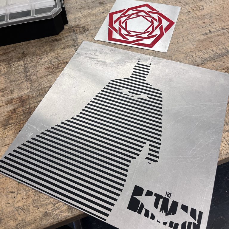
I made using the vinyl cutter was two posters. I cut aluminum sheets using the DesignPlus metal laser cutter and designed some graphics using google references, paint.net, and Adobe Illustrator. The process was simple, as I could accurately control the sizes of the sheets. I could size and cut the poster graphics to fit the aluminum backing boards and align them using the leftover vinyl from the stencil.
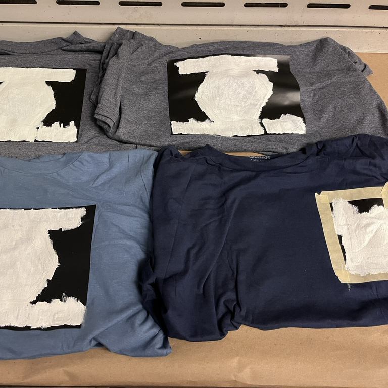
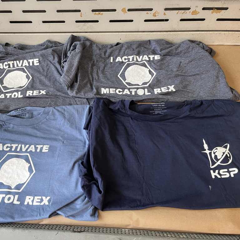
was a small batch of shirts inspired by the board game Twilight Imperium for my playing group. As before, I found some reference images on Google and edited and created stencils using paint.net and Illustrator before cutting them out on the vinyl cutter and printing them in D-Lab.
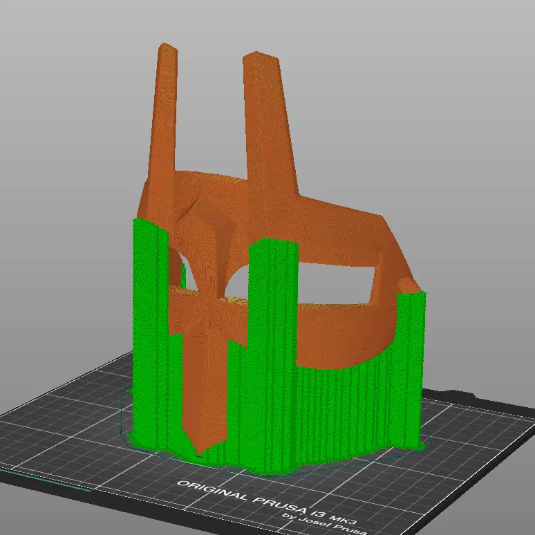
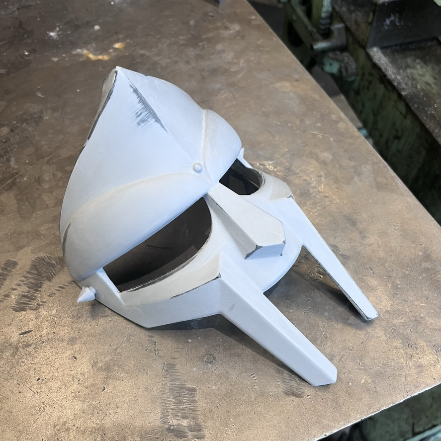
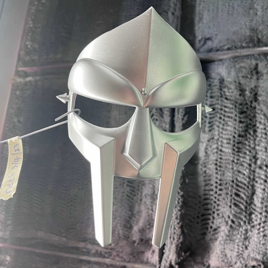
of Daniel Dumile's (MF DOOM) gladiator mask. I have always wanted to make an aesthetic piece out of something that was 3D printed, so when I heard of the passing of the Madvillan, I wanted to make this project my introduction to finishing 3D prints and a tribute to him as a fan.
a model of the gladiator mask I found on Thingiverse or somewhere online. I followed a YouTube tutorial using automotive filler spray paint and a range of sandpaper from 200-1400 grit. The tutorial also called for using Bondo filler putty, but there weren't any sections that I deemed required this part, so I skipped it during the finishing process.
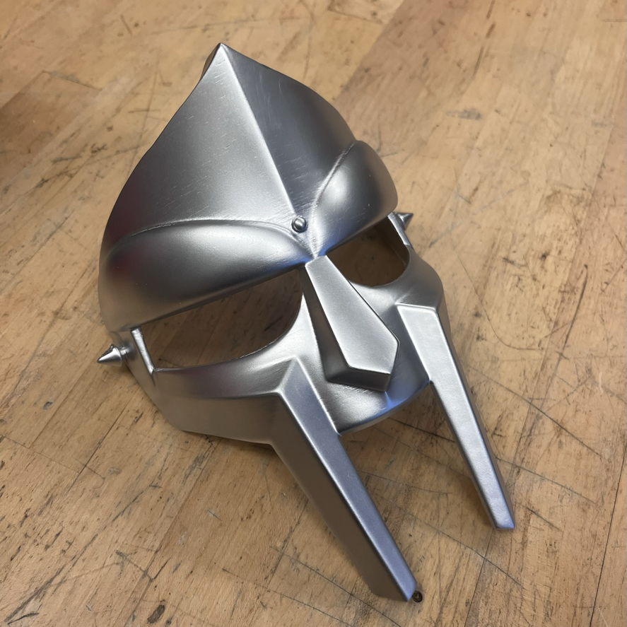
I initially sanded the model with low-grit sandpaper before applying a few coats of the automotive filler primer. After sanding and repeating this another time or two, I sprayed on a few coats of metallic-colored paint to get the iconic look.
Overall, I'm pretty happy with how the piece came out. I know some imperfections with some of the finish, but I think they all add to the mask's personality. Making this mask was a great experience in learning how to finish 3D prints, and I look forward to the next opportunity to apply what I learned during this short project.
instead, it's a collection of little things that I feel didn't deserve a full feature.
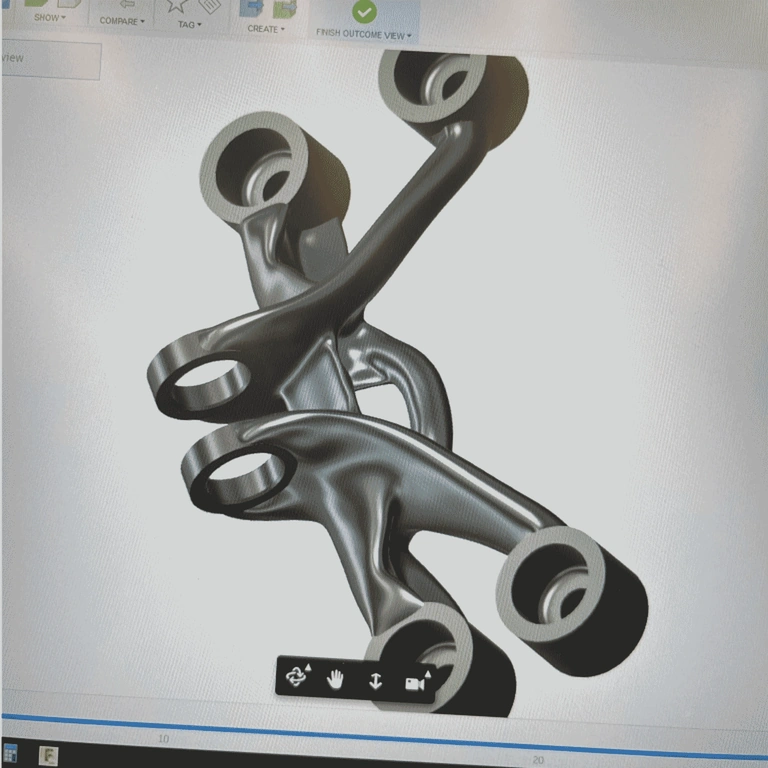
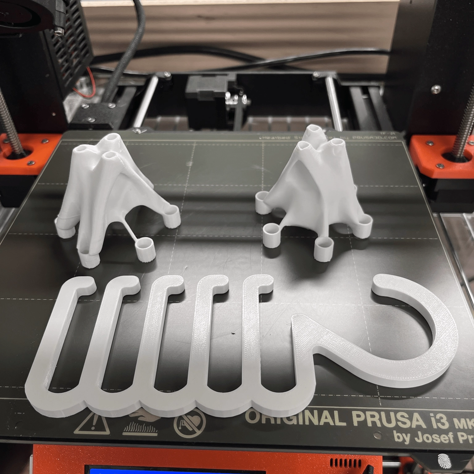
This picture is the default model for the Fusion360 finite element analysis (FEA) tutorial. I took this photo when I was looking to make a stronger motor mount for my scooter after having rigidity issues. I knew I wouldn't use FEA, but it was a fun exercise.
Here is when I 3D-printed some different FEA models I made using the same method in fusion. To make the print job at the Metropolis makerspace not entirely frivolous, I also threw in a tie hangar.
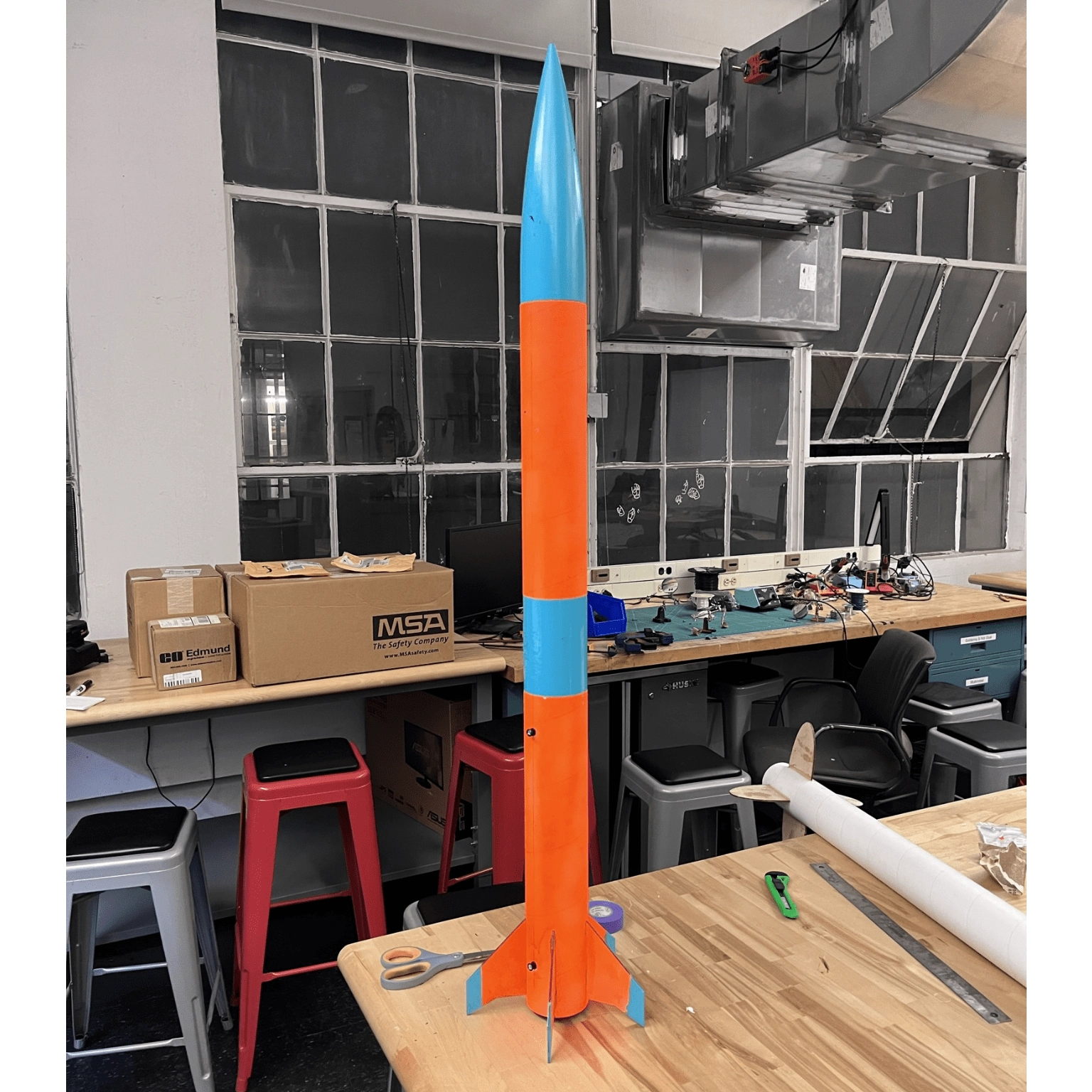
This was the L1 rocket I made through MIT Rocket Team for my L1 Certification with the National Rocket Association. Long story short, I couldn't make the launches during my first year at MIT, and my rocket was eventually trashed with some others. I'm not sure if I'll ever remake an L1, but at least I'll know how to.
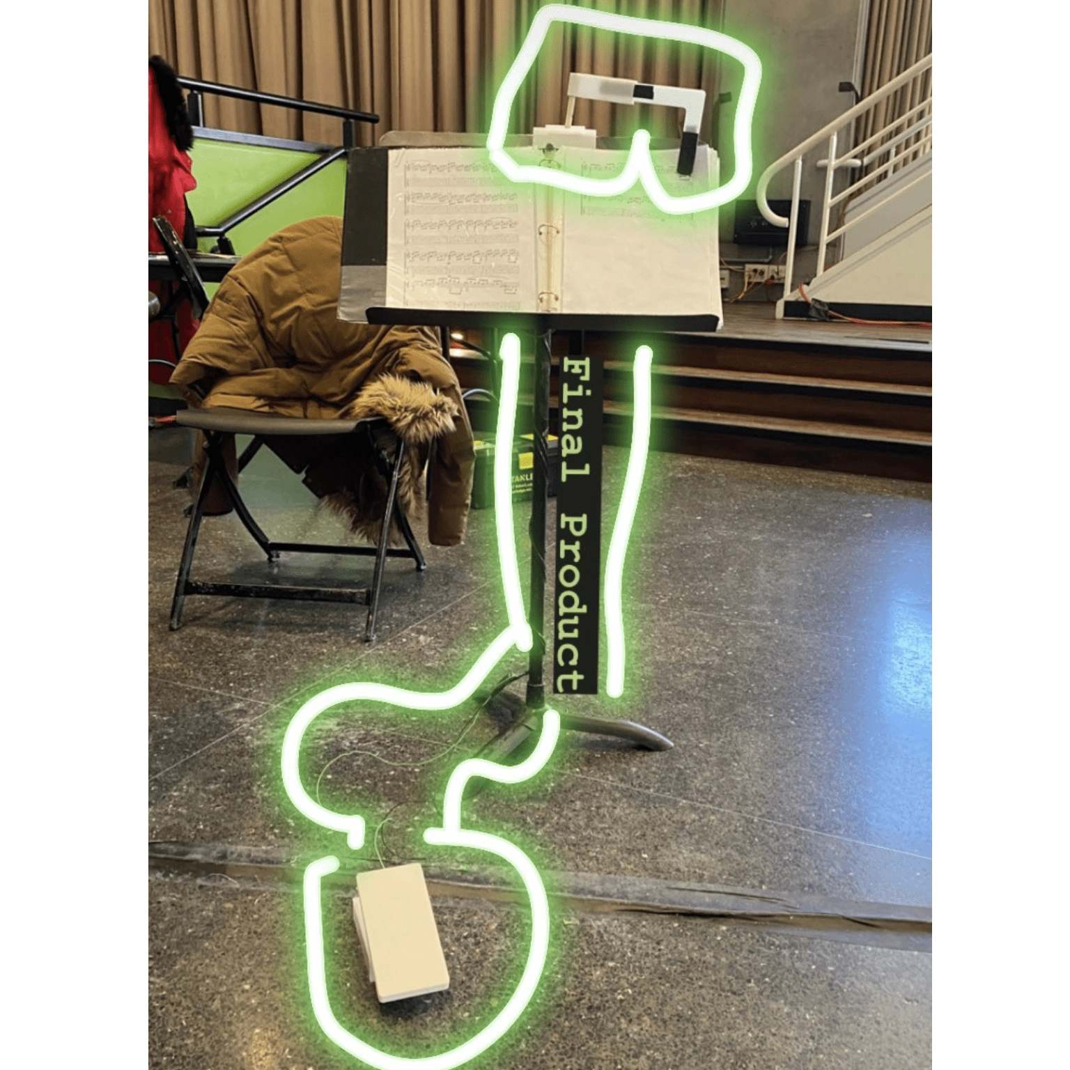
This was my group's submission for MakeMIT 2022. The product is a foot-pedal-actuated music sheet flipper. You can't see it from the photo, but the foot pedal in the foreground is connected to a control box hung behind the music stand with two servos that move the flipping arm up and down and around the axis of rotation. I contributed by designing, cutting, and building the flipping arm, foot pedal box, and control box out of acrylic.
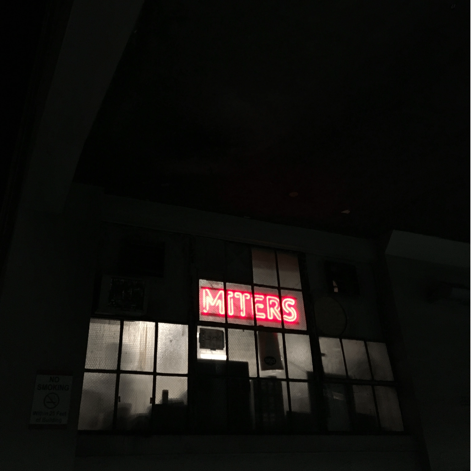
Not much else behind this photo, but I will give some background about MITERS. The MIT Electronic Research Society (MITERS) is an MIT community makerspace run by students for students. I have made most of my projects there starting my first-year fall, and I was lucky enough to be knighted as a keyholder in Jan 2022. Since then, I've been happily working there on my current projects and helping out when I can.
instead, it's a collection of little things that I feel didn't deserve a full feature.
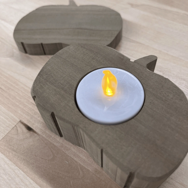
This is a little wooden (not sure which variety of tree) holder I made in an MIT Makerlodge training session. The design uses an electronic tealight since real flames are not allowed in my dorm. I made this around October 2021, which makes sense, given the Halloween-Esque design choice.
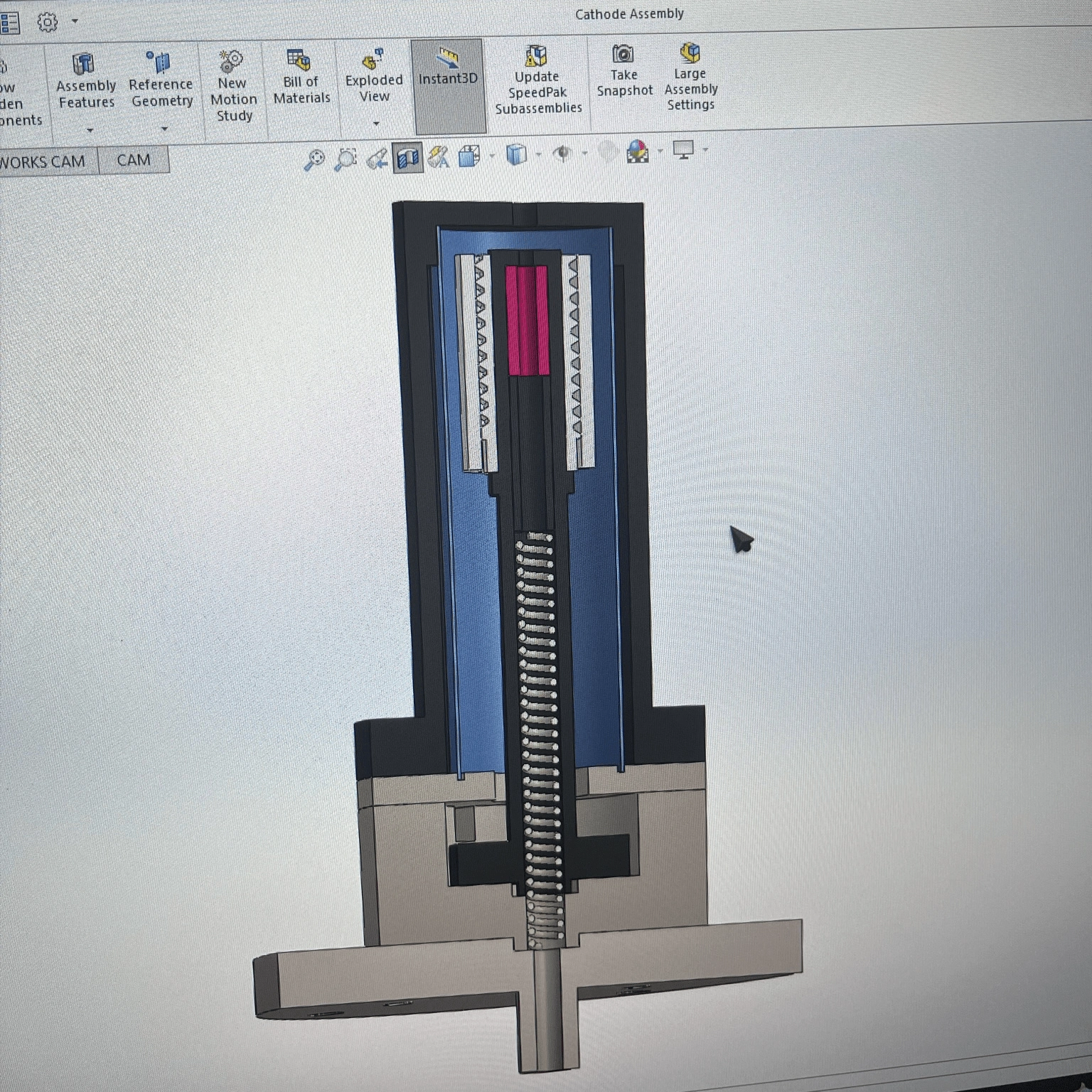
This work was for my very first UROP in the MIT Space Propulsion Laboratory (SPL). Here I was designing and prototyping a hollow tube cathode for plasma generation. The design in the picture is a recreation of the cathode designed by Daniel Courtney.
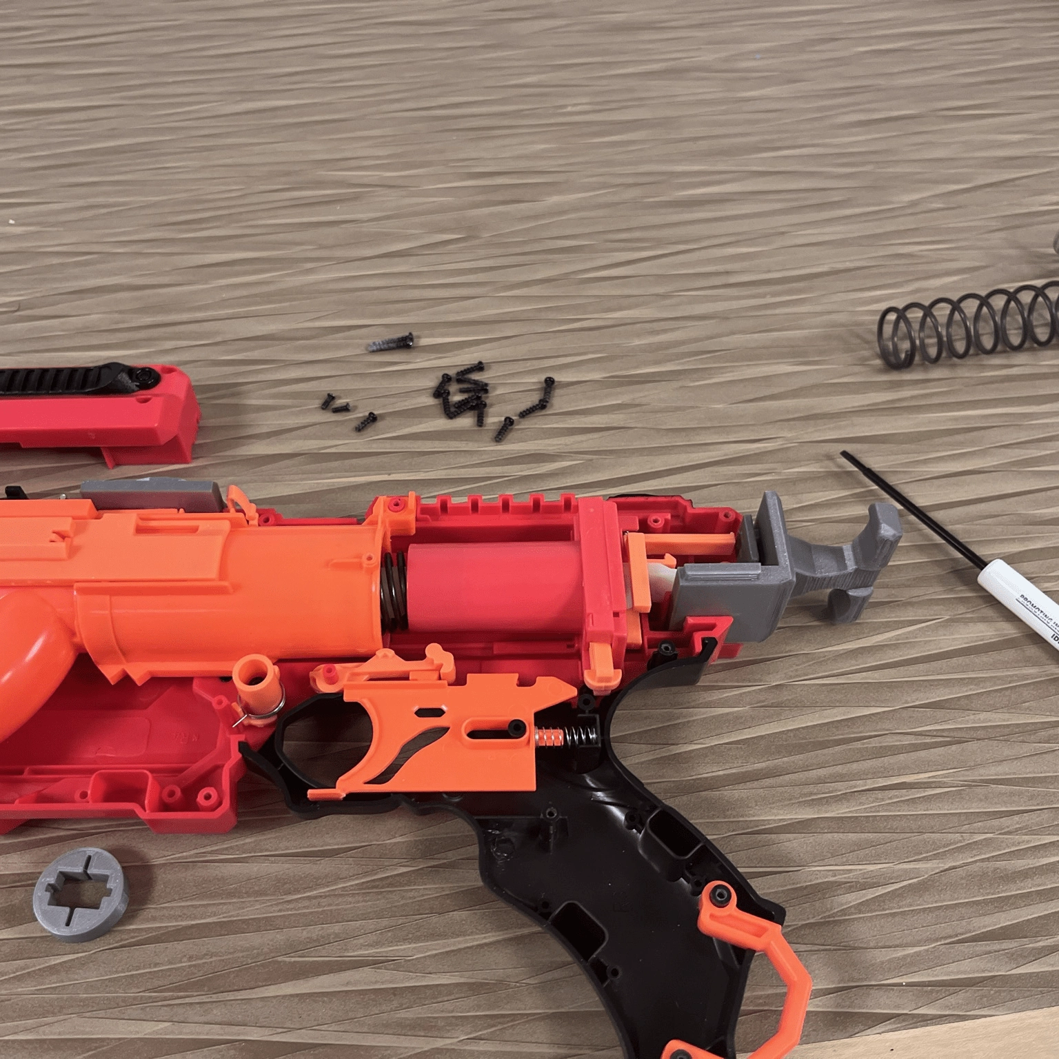
Just a quick photo of when I was making some modifications to a NERF Kronos for my final project/experiment for the class 8.01L, 21' fall. Adding some helpful QOL features like an extended charging handle and swapping the spring out per our experiment procedure.